Phi-2 shield

Where to buy:
Buy directly from me:
You can place an order right here for a kit or follow the link below to visit online stores to make your purchase, with more options and purchase other hardware I sell:
 Out of stock (including LCD)

Out of stock (including LCD)
Buy from online stores:
There are more options you can buy at online stores but you do need to register at some of these stores.
Please click this link to redirect to the “buy” page for where to purchase this hardware.
Introduction
Congratulations on getting the best all-purpose interactive shield for Arduino! You are not just getting a piece of hardware; you’ve just got the best interactive user interface software package, phi_prompt, and the best support!
There are two variants of the phi-2 shield, the standard shield with 16X2 display, and the 2004 shield with 20X4 display.
List of its functions:
- Compatible with official Arduino Ethernet shield with SD card.
- 16X2 LCD or 20X4 LCD (2004 model) character display.
- 6 push buttons – four arranged like a control pad with four as arrow keys and two more on the side.
- 2 RJ45 ports to pass as many as 16 long and robust connections to sensors or control devices.
- Optional buzzer in place of an RJ45 for tones. You can connect any arduino pin to the buzzer.
- Optional sensor block to sense most common sensors, such as thermistors for temperature, resistive pressure sensors, light-dependent resistor for light, Hall effect magnetic sensors etc. You can connect any arduino pin to the buzzer.
- Two 3mm LEDs as indicators. You are free to choose which arduino pin to drive the LEDs with.
- Real time clock with battery backup keeps the time when Arduino is turned off
- EEPROM for easy data logging keeps data when Arduino is turned off (http://search.digikey.com/scripts/DkSearch/dksus.dll?Detail&name=24LC256-I/P-ND or http://search.digikey.com/scripts/DkSearch/dksus.dll?Detail&name=24LC512-I/P-ND)
- GPS connector and breakout for this popular GPS module
(http://www.sparkfun.com/commerce/product_info.php?products_id=465) - Reset button for Arduino
- All Arduino pins are brought out for maximal flexibility.
- The I2C bus is not tied to arduino UNO or Deumilanove analog pins 4 and 5 but brought next to them so the shield can be used on a MEGA. Just jump them to MEGA 20 and 21.
Documentation:
Videos
Phi_prompt demo video play list
Phi-2 shield projects video play list
Picture gallery


Complete projects with code to get you started:
I am converting all my Phi-1 shield projects to Phi-2 shield project codes. This could take some time so please be patient.
To run these codes, make sure you set your display size correctly so that the information displays correctly.
All codes are hosted on Google code page . Please browse the list and download the source codes here :
http://code.google.com/p/phi-prompt-user-interface-library/
New codes that are compatible with arduino 1.0 needs these libraries phi_interfaces 1.0 and phi_prompt 1.0.
Older codes that are compatible with arduino 0022 (I’m converting them to 1.0) need phi_buttons 327 version and phi_prompts 523 version. Please download and install new libraries and new codes if you are using arduino 1.0 or the older libraries if you are using arduino 0022.
List of projects:
- GPS interactive data logger 5.0 (needs update)
- Alarm clock V 1.6 works best on 20X4 shields (download)
- Morse code translator 1.6 (download)
- Testing all functions (gives you a sample of how to use everything)
- Car reverse obstacle sensor (Still being updated to use phi_prompt 523 version)
- Password input panel (Still being updated to use phi_prompt 523 version)
- The list keeps growing…
Possible projects to get you thinking:
- Standalone or PC data logger
- Lab data acquisition system (Physics, Chemistry etc)
- Weather station
- Input or operating panel, like security panels or garage door opener
- Handheld GPS
- Tweet update display (with Arduino Ethernet shield)
- Interconnected network of arduinos over serial ports
- The list goes on…
Where to buy:
Please click this link to redirect to the “buy” page for where to purchase this hardware.
Dependent software libraries
Phi_prompt, phi_interfaces, some projects need phi_big_font to display bigger font on text LCDs
Changes from Phi-1 shield and new features:
Old: Two RJ11 jacks. Power, GND and one analog channel are hardwired to each jack although you can hack them.
New: Two RJ45 jacks replace the two RJ11 jacks. All 8 pins on each jack are broken out and there are 5v and gnd near each jack for easy access to power and ground. It’s more work on the user but offers more flexibility.
——
Old: Buzzer is hardwired to analog pin 2. An LED is hardwired to analog pin 3.
New: The LED is removed and replaced by two smaller ones above analog pin headers. The,LEDs, the buzzer and sensor block are not hardwired to arduino pins but to female headers, so you can jump them to any pin. It’s more work on the user but offers more flexibility.
——
Old: The real time clock and EEPROM chips are hanging below the board.
New: The two chips are now on top of the board to give more clearance below the board to work better with more shield boards.
——
Old: The SDA and SCL line of the I2C communication are hardwired to arduino analog 4 and 5.
New: The SDA and SCL lines are brought to female headers, right next to the arduino analog 4 and 5. Jumping them to analog 4 and 5 works with Duemilanove and UNO, while jumping them to 20 and 21 will work with MEGAs. You don’t have to give up MEGA’s two analog pins to use I2C.
——
Old: 5mm LED.
New: A sensor block replaces the 5mm LED, while two 3mm LEDs are added elsewhere. The sensor block is a universal adapter to many analog and digital sensors. The three rows of 3-pin female headers are connected in the following way:

Many sensors have 3 pins, 5V, GND, and signal. With this sensor block, you can test any of them without having to twist their pins. To sense analog IC, hook the bottom right pin on the 5-pin header to analog pins. You can also use the sensor block for purely resistive 2-pin sensors, such as thermistors for temperature, resistive pressure sensors, light-dependent resistor for light, Hall effect magnetic sensors etc. Just hook the sensor in series with these sensors in the following diagram.


Application notes
Using RJ45 for bother powering and controlling/sensing a device
To reduce contact resistance on the crimped cable, you can use multiple wires in the RJ45 cable to pass power and gnd. Say you only need to control one servo motor, then you can chain 3 wires of the RJ45 together to pass power, 3 wires together to pass gnd, and 2 together to pass sensor.
If you plan to run both sensor and power down the same wire, you should put some filter capacitors between the power and gnd, to prevent the power to couple with sensor. In a project I did, I had to put a 1uF cap for my sonic ranger to work on 12ft of phone cord.
http://liudresllc.com/2011/02/12/arduino-parking-sensor/
Test code:
Please follow the documentation section 11 for testing.
Phi shields are on the map!
Since there have been over one hundred users of the Phi-1 and Phi-2 shields, I decided to create this Arduino Phi shields users’ map so that we can share who’s out there doing what projects with the shields. So potentially interested individuals can share projects and or codes!
Click here to add yourself to the map.
Directions to add yourself to the map:
1) Click the above link.
2) Press the edit button on the left.
3) Click the middle button and place a blue pin on the map to indicate your approximate location
 4) Once you place a pin, you can edit its contents. Then click on the blue pin on the top right corner (boxed up by a blue square) of the dialog to change it to a symbol you want.

5) Click save on the left side and then done.
Pingback: Phi-menu is about to be released! « Liudr's Blog
Hi Dr. Liu,
I am part of a team that is working on developing an electrical muscle stimulator (for proof-of-concept of course, we wouldn’t be using it on anyone) for our engineering senior project through using an Arduino Uno board and were interested in using your phi-2 shield in developing an interactive menu that could be used to change the parameters of our output waveform. We were interested in ordering one of your phi-shield kits and wanted to know when they would be available.
Your site is amazing, keep up the good work!
Thank you for your help.
Erik,
I just received the first batch of Phi-2 shields. I can mail you a kit if you have paypal account. I’m in MN. Please see email I sent you.
Hi All.
I’m probably “the perfect newbie” in this Arduino/shield world, so please be patient with me!!!
I’ve just purchase a couple of your Phi 2 Shields intended to build a couple of projects that I have in mind some time ago but… I also have a couple of LCDs and a shield that uses LCD4Bit libraries and I wonder if I could use it also with your libraries…
You mentioned that it is possible but with some changes in the sketch, but I’m not sure about which modifications should I do in order to make this stuff working properly…
Any advise will be very helpful and welcomed!!!
I’ll keep you all posted with my progress!!
Main idea is to use it to stablish a good menu system to control a couple of DC/Stepper/Servo motors, and give relevant info about motors parameters (speed, temperature, stalling times, etc…)
Thanks for your patience!
Regards
Paco,
The LCD4Bit library, en, could be this shield?
http://www.robotshop.com/dfrobot-lcd-keypad-shield-arduino-1.html
The LCD 4Bit library is probably several years old and should not be used anymore. The arduino IDE carries its standard LiquidCrystal library as far as I could remember. Please dump the 4bit library and use the standard library 🙂
If you use the arduino standard lcd library, nothing needs to be changed. You can load the alarm clock code or test code and get it ready to go. Just remember before using the real time clock, set it up first. I just replied to AC about this question. My phi_prompt library should take care of menu of any style you desire and any level of menus. Watch a few videos of the phi_prompt library you will find out.
Hello:
I would like to know if you could sell me a phi-2-shield board pcb instead of a full kit?
If so how much, including shipping to Portugal.
Best Regards
Steve Sousa
Thanks for you interest Steve. The shield board itself is $12. I would like to charge $3 shipping and handling. I’ve sent you an email. Please check.
Hi Dr. Liu,
I hope I am not too late but I would like to purchase one Phi-2 shield kit from you…if you still have any available. I’m loving the Phi-1 shields I already purchased and cannot wait to get my hands on the Phi-2.
Thank you very much for designing an awesome Arduino shield and for having such a well documented web site.
Have an OUTSTANDING day!
Patrick Shay
Patrick,
Nice to hear from you again! I’m glad that you like my design. Yes I still have several kits I can mail out. Please paypal me $28 and I will ship you one full kit (+some random extra parts for tinkering).
Liudr
Hello Dr Liu,
Could you please point me to a phi 2 schematic? I’m assembling my first one and I want to be sure that I understand all the connections. An image file will do: I use DesignSpark, not Eagle.
Thanks for buying the phi-2 shield!
If you need some instructions on assembling, check out the documentation.
http://liudr.files.wordpress.com/2011/02/phi-2-documentation-04022011.pdf
Read page 8 for assembly instructions. You may find figure 14-1 on page 15 helpful.
I had previously found and studied these instructions, thanks. There are just a few things I’m not 100% clear on and a schematic would save me (and others) some testing, if you should happen to get around to adding it to the already excellent on-line documentation some time.
Hello Dr Liu,
I am having some trouble with the test code. When I try to verify and compile, I get the fault: “‘wait_on_escape’ was not declared in this scope”. I would be very grateful if you could please point out the nature of the dumb newbie mistake I have made.
Doug,
The test code needs support from the following libraries:
phi_buttons, which handles buttons class objects: download them on my libraries pages.
phi_prompt, which handles user interactions or user interface with lcd and buttons if you want to run some examples with menus and number or lists: download them on my libraries pages.
Let me know if you have trouble installing the libraries.
BTW, I will consider posting the diagram of the shield. I just fear some copy cats will take it and make a hundred copies and sell them for half of my asking price, which is very low considering how much software support I offer. That would be bad. What part of the shield connections do you want to know? I’m willing to explain 🙂
Hello again,
I worked out that I have to add “EEPROM” and “functions” to “Phi_2_testing_V1”. Doh.
“Phi_buttons_example_01” and all the “Phi_prompt_example_xxxx” sketches work with no problems at all. Awesome software support – you’ve done all the work already!!! Great for a “cut and paste” guy like me.
While I was blundering around in confusion, I noticed that “phi_prompt” wasn’t highlighted like the other libraries. Is it possible that the first line of the keywords.txt file for phi_prompt should be:
“phi_prompt KEYWORD1”
not
“phi_prompt_struct KEYWORD1”?
I completely understand your concern regarding posting a schematic. Don’t worry about posting it – I have not come across anything yet on the board that I can’t work out myself but if I do, I’ll let you know.
After all, working it out is half the fun!
Thaks for your help
Cheers
Doug
Doug,
I am very happy to know that you have worked out the problems and start enjoying the hardware and software! Thanks for your compliments. I try to do as much as possible in regarding to software support after the hardware. I don’t know of any other individual or place that does this level of support. Please go ahead and modify the keyword file. My reason was that phi_prompt was not a class but rather a utility function library so I didn’t include it in the keywords, rather I included phi_prompt_struct, which is a defined type.
I am in the process of planning for some update on the phi_prompt library, to include more features. Please feel free to drop a few lines of comments. I am guessing that your line of work is related to computer software. I have not seen anyone blazing through code as fast as you did:)
Hi, I am having a problem with the shield not recognizing when the buttons are pressed even though I have check them with a multi-meter and they seem to work. Which ground pin are they connected to? I created a code to test the buttons by printing the button name on the LCD when that button is pushed. It doesn’t work except for when i jiggle the shield, then it goes crazy.
Any help would be appreciated. Also, If you copyright the Phi-2 design, no one could legally take your schematic and reproduce it.
Thanks, Eric
Revision to my earlier statement. I figured out the wiring of the buttons but cant open the Phi testing version 3 because it is not a valid windows 32 application. Is the Phi_2_testing_v3.pde a windows 64 file?
Eric
You need to open it inside arduino IDE. Any future saving will turn it into themore current file extension .ino.
Actually, I’m an industrial electrician with a smattering of “C” and a fair bit of experience with exploring a wide range of unfamiliar control systems and programs. Very much a generalist. As a result, I tend to solve problems simply by blundering about looking for points of difference between non-functioning code and similar functioning code. This type of ameturish “proto-hacking” tends to lead me into places that somebody with a better level of understanding wouldn’t bother to look – like obscure text files in odd sub-directories 🙂
Sorry to bust the illusion of “blazing through code”!
I am getting nothing on the display. Is the supposed to be a backlight? I have probed and it is getting 5v power, played with pot, and still nothing on display.
Test code compiles and downloads successfully – no error messages.
Arduino seems to be funcitoning – I can run other sketches with the shield attached.
Can you provide more startup debugging help – or give clues that might help me investigate why the shield is not functioning.
-AC
AC:
If you load the blink example from arduino ide example folder (any basic example will work) to your arduino while having the phi-2 shield on, do you see a row of black boxes on the display?
If not, you need to adjust the potentiometer until you see the black boxes to ensure your pot is set correctly.
If you can see the boxes, please check your test code to see if you downloaded the phi-2 version or not. The phi-2 version is here:
http://www.mediafire.com/?1rjh8raf3w0svx7
Make sure in the code this line is correct.
#define LCD_D7 3
Let me know if you solved the problem or not. Thanks.
I can not see the boxes when running the blink program. I twisted the pot 40-60 revolutions and still no boxes. In what direction should I turn the pot? I tried both, but saw nothing.
The lcd display does a very dim backlight. I verified this in a dark room. I can definitely see the display glow when I plug in the arduino board.
Any more ideas?
Dim back light is correct. You can make it brighter if you reduce the fix resistor soldered on the top left side but the thing is if you prefer showing a back light brightly lit, it’s annoying to the user. The back light is meant for users to read in dark.
Do you have a multimeter to test the voltage on the pot? Can you post a picture showing details of the solder job on the LCD and the female headers for the LCD? If the pot works then the voltage should change as you turn the pot. If it doesn’t, something is wrong. If you soldered all pins nicely, the LCD should should the boxes on power up with the right pot setting. Let’s start with pictures so I don’t have to second-guess your solder job.
Ohhh I got it working. It was the potentiometer… I turned it about 15 revolutions counter clockwise and I could then see the boxes. Downloaded the test code and ran through all the tests… The buzzer did not work, but I expected that – I need to find a resistor.
High five!
Please do get back to me if you make progress on projects you intend to do with the shield!
I’m updating the phi_prompt text-user-interface library. Check it out later tomorrow for the new release. Lots of stuff are included to make arduino with lcd and keys like a small computer.
I left the EPROM socket empty and I did not put in a resistor for the buzzer – I wanted to try several different ones to get a good loud tone. Are any of these things required for the display and buttons to function?
-AC
Those don’t affect the LCD. But a few pictures will help.
Liudr,
I am not able to set or get data from the rtc. I checked the socket, orientation, and voltage (4.9v) on the DS1307 vcc pin.
I hacked your example code to insert a short test loop to get minute of day, but I see only “0”, it never gets good data:
void loop()
{
char msg[17];
lcd.clear();
sprintf(msg, “%2d”, RTC.min_of_day( true ) );
lcd.print(msg);
delay(30000); // 30 sec delay
}
Is there anything I can do to see if the rtc chip is operating?
-AC
Can the 32.768kHz Crystal be installed in any direction? Is it possible to test that it is working?
-AC
Yes, either direction works. I think you probably didn’t read very carefully my example code on how to initialize the real time clock, number 2:
Instructions:
0. Please download phi_buttons library (http://liudr.wordpress.com/phi_buttons/) and unzip the three files and example subfolders in arduino\sketchbooks\libraries\phi_buttons\
1. Please download phi_prompt library (http://liudr.wordpress.com/phi_prompt/) and unzip the three files and example subfolders in arduino\sketchbooks\libraries\phi_prompt\
2. You need to set the clock before you can use it. Uncomment this line “#define setRTC” among the #define lines.
3. Update the time in setup() to the current time.
4. Upload the sketch to arduino to set the time.
5. Then comment the line “#define setRTC” and recompile and upload to arduino.
6. If you don’t do step 4, the clock will be reset every time arduino resets.
Give it a try.
Liudr,
I have tried your instructions, exactly:
uncomment #define setRTC, load the sketch, when I see ‘Testing all keys’ on the lcd display, I re-commented the #define setRTC, uploaded the sketch, went through the button test functions, but the clock test shows ‘eek/00/2000 A–‘ ‘ 0:00:00’
Can you provide any other clues as to how to debug the clock problem. I have checked the socket, pulled the chip and reinserted, checked that the pins are making good contact, checked that the half circle indicator is “up”, and the voltage is about 5v at the chip.
-AC
OK. How about the jumpers between the arduino analog 4, 5 and the SCL SDA header?
http://liudr.wordpress.com/shields/phi-2-shield/slide2/
Bottom right analog 0-5 headers. The female headers above that header has the SCL and SDA lines, the very right two. You need to jump them to analog 4 and 5.
See the shiny jumpers in this picture?
http://liudr.wordpress.com/shields/phi-2-shield/slide3/
What about the battery? The positive sign on the battery should face up. And the battery holder’s “knob” points up too. The RTC chip socket is the right socket. Its half circle points up. If you can get a picture up, it’ll also help me identify problems.
No I did not see the jumpers before. Now I have them in place. Uncommented #define setRTC, loaded sketch, and it shows ‘h’ on the lcd. Did not see that before…
Now commented #define setRTC, loaded sketch….
Still see ‘h’ on the lcd – it does not go to ‘Testing all keys…’
Pics here:
http://fivehundredhorsepower.wordpress.com/2011/05/26/shield-pics
ARRRR!! I’m so stupid. I loaded the wrong sketch…. What a bonehead.
With the correct sketch, and the jumpers in place, I NOW HAVE A WORKING CLOCK!!!
woo hoo.
Thanks for your awesome help.
-AC
Haha! Finally it is working! Awesome! Hey that wasn’t bad for me at all. So happy you got it to work. If you want to alarm, you need a resistor for the buzzer 🙂
Hey! Which project sketch did you use?
Thanks!
Hi Kaye,
Sorry for the delay in response. I only can respond to comments about once a week or so. I just created a video of how to download and install the libraries and code so that they will compile. Next step is to select what arduino board you have on which serial port so you can upload to it. Let me know if you have more questions.
https://youtu.be/mESfWvpa1cY
Hi again, Dr,
I’m trying to put the shield working, but I am experiencing some problems:
First, I have NO backlight in the LCD Display. I have substituted and even removed (but jumped) the LCD resistor, but no way.
Second, I’m unable to upload any of the examples you provide. I received an error when compile:
init_phi_prompt was not declared in this scope.
And third, if I try to install the shield on to a Mega, only “down” button works properly.
Additionally, I have developed a routine to input the system with a rotary decoder. The problem here is that I need to use an “interrupt” function that uses digital pin 2 (interrupt 0).
I’ve tried to use my Mega instead the duemilanove (because I can use different interrupts apart from digital pins 2 and 3), but then I have the problem with buttons …
Too many problems!!
Any help would be welcomed.
Regards
Paco,
Let’s attack one problem at a time. If you don’t have back light, did you connect the correct back light resistor at the top left of the shield? I could look at your picture. Jumping the lcd resistor isn’t a good solution. The back light could burn out.
Does the LCD show a row of black boxes after you adjust the potentiometer?
You will need to download the latest version of the library. I think you did but can you tell me what directory the library is in? It needs to be at sketchbooks\libraries\phi_prompt, not sketchbooks\libraries\phi_prompt\phi_prompt or libraries\phi_prompt.
The “only down works” worries me. I would request a couple pictures of the shield to see if there is anything wrong.
The pin 2 can be moved elsewhere but let’s solve the first few problems before making a decision to handle this issue.
Hey Liudr,
I’m enjoying my Phi-2. It seems to work properly as the test codes executes properly and many of the examples have worked until I tried the Phi-2 Alarm Clock V2 app. It generates a large number of errors on the line ” msg_lcd(msg_00,&lcd1);”. Any thoughts would be most appreciated. It looks like a dependency issue but I’m not seeing it.
I want to take a minute and thank you for your work on the Phi-2, it’s a great spring board to many other Arduino projects.
Cheers,
Steve
Steve,
I was in the process to update all my codes to work with the new Phi_prompt library release. In the new release, you don’t have to do msg_lcd(msg_00,&lcd1);, just msg_lcd(msg_00); but the library does need to be initialized so it knows the lcd and buttons. See this page for all the details:
Phi_prompt page
Since you asked, I’ve just finished the update on the alarm clock program code. Please download the new code on the Phi-2 shield page again!
Thanks Liudr,
Version 3 of Phi-2 Alarm Clock solved the problem.
Steve
Glad to help. I’ve updated the phi_morse library with a Morse translator to a new version too! Check it out if you like. You need no extra hardware to run it.
Felt silly today as the “year” couldn’t be changed in the alarm clock. Found out one simple mistake and fixed it. Now version 4 is just uploaded with maybe 3 bytes different 😉
can this project produce voice just like the “hello world” ? i’m working on my final year project which the title is communication aid for speech disabled people using morse codification . really need your suggestion on how am i supposed to produce voice/speech using arduino .. tq
The on board buzzer can only produce monotonic sounds and will produce Morse audio easily. But to generate human voice is a whole different story. You need large storage of voice and elaborate program to turn text to speech (TTS). Arduino doesn’t have enough memory to to any of that. Unless you play pre-recorded sounds with some wave shields I don’t know what to do to do text to speech, i.e. turn any text into speech. There should be chips that do this at a cost.
how about spelling the display text like H e l l o?.. i’m interested to learn the morse code after seeing this blog but i have no idea on how to do my fyp project . learning morse code is easy but to produce voice is so much complicated for me , especially i’m very new with arduino .and what is the main purpose of learning the morse code for this 21st century?
That is doable. The phi_morse library has two important functions:
One is morse_out(). You send it a string, and it plays out the da and di on a buzzer. So if you want H E L L O (Morse has no lower case letters), then you can do:
morse_out(“H”);
delay(500);
morse_out(“E”);
delay(500);
…
So that the letters are played and a pause between every two letters.
You do need to initialize the morse library by telling it which pins are connected to the buzzer and the input key.
Morse code can be transmitted over very noisy channels or even used with lights over great distances. I know it has been dropped by lots of certification programs for say hobby radio operators and what not but it can be useful when everything else fails. You can understand morse code without using a computer.
If you get the phi-2 shield, you will get all the required hardware to produce morse sounds and input morse code to test your skills too. The morse-in() function in my morse library will take care of interpreting your inputs.
For generating voice, it is a completely separate question. I wish I had answers to that.
Sorry try a last time 🙂
Hi Dr. Liu,
Have just implementet your code its great but in the menu i get wrong sign.
Where have you defindet the ascii code for this ?
My menu looks like this
£ Load file
~ Upload to PC
£ Set Menu Style
This is what it should look like ?
● Load file
→ Upload to PC
● Set Menu Style
Yes your menu should look like the dot and arrow instead of Franks and twiddle.
Have you run the initialization function?
init_phi_prompt(&lcd,btns,lcd_columns, lcd_rows, ‘~’);
The ‘~’ is what symbol the library will use as indicators. On an HD44780 display the ‘~’ as an arrow. Can you provide me a picture of the menu as on your display and the model and manufacturer of the display?
Yes i run the init string
init_phi_prompt(&lcd,btns,lcd_columns, lcd_rows, ‘~’);
My display is
G M S
MSH2004L-YYB-ET
CQC OK 06/03/05-61
if you mail me you mailaddress i can send a picture
The following are posted from email communications with Ole:
8/23/2011
Ole,
According to the datasheet of your display, it uses KS0066 display controller, which is compatible but not entirely equivalent to the more standard HD44780 display.
Here is a datasheet I found on the controller:
http://www.datasheetarchive.com/dl/Datasheets-110/DSAP002411.pdf
On page 22 with the standard character pattern KS0066F06, the spot for arrow is replaced by the “~”, and the place for a center dot is replaced by a scripting f.
Unfortunately for this character set, there is no arrows at all and no center dot either. If you initialize with ‘>’ instead of ‘~’, you will be able to use ‘>’ to indicate active list item. For inactive list items that should show dots, I will further investigate an alternative possibly in my next library release. Meanwhile I’ll find where the dot was used and tell you how to modify this current library to get it to work 😉
8/24/2011
Open the phi_prompt.cpp and search for \xA5 and replace with a character you like as the bullet of the items not being highlighted. It should only appear once in the file right in the middle of the code.
Please let me know how this fix goes and I’m interested in your project with my library too. If you have a link to your website or blog for this project, I’d like to cross reference on my library page 🙂
Since you posted another one so should I discard this comment then?
Am working on a project and am thinking about using Serial 20X4 LCD keypad panel – Phi-panel
for getting and displaying data. I want to be able to type in code like I do on my phone. There is no information about the pins that are used in the atmel328 chip. This information would be helpful in my design and schematics would be useful too. Let me know so that I can get the kit ordered ASAP and start working with it.
DK
Hi DK,
You don’t really need to have any code to run this panel with your intended use since all the hard work is done by the panel’s on-board processor. Say you want multi-tap input so you can enter messages/code and your arduino receives it, here is what to do for software:
Call the following function with a char array as the buffer. The function enables multi-tap on the panel until you finish and press enter. It then disables the multi-tap and returns you the user entered info:
char buffer[50];
get_text(buffer);
void get_text(char in_char[]) // Uses multi-tap and understands backspace and enter
{
int i=0; // Input buffer pointer
Serial.write(14); // Turn on multi-tap.
while(1) {
if (Serial.available()) {
in_char[i]=Serial.read(); // Read in one character
Serial.write(in_char[i]); // Echo key press back to the panel.
if ((in_char[i]==’\b’)&&(i>0)) i-=2; // Handles back space.
if (in_char[i]==’\n’) { // The \n represents enter key.
in_char[i]=0; // Terminate the string with 0.
Serial.write(15); // Turn off multi-tap.
break; // This breaks out of the while(1) loop.
}
i++;
if (i63) break;
}
}
}
All you have to do for hardware is connect the panel to arduino serial. I suggest connect to arduino with NewSoftSerial so you don’t have to disconnect the panel while programming arduino.
Here is a video of the multi-tap at work
Advance to 2:32 to see it. All arduino needs to do is to tell the panel to use multi-tap (see the function) and receive characters like it has a full size keyboard.
regarding from my previous comment about producing voice from this mini library.
can this things works with this?
http://www.ladyada.net/make/waveshield/
really2 need ur help sir.
This is a shield that plays pre-recorded messages. What you need is an audio synthesis chip that constructs voice out of text message. That shield can’t do that.
how about using speakjet or xbee?
Is this what you are referring to?
http://www.sparkfun.com/products/9578
This chip just requires a serial link to it so you can use any unused pins by the phi-2 shield to drive it. You can also just connect its output to the buzzer, which is not tied to an arduino pin.
xbee uses serial port, so same applies. You may need to check if the bee’s antenna is too long to stick up too much.
need some guide here..i just found one morse code decoder project on this website http://www.nerdkits.com/videos/morsedecoder/
is there any voice synthesizer that can be used to make it speak..?
tq.
Maybe using these two chips together?
http://www.sparkfun.com/products/9578
http://www.sparkfun.com/products/9811
I don’t really know.
i also found that those two things works with arduino in this
http://letsmakerobots.com/files/SpeakJetTTS_Schematic.PNG
but it doesn’t have lcd display and i dont know how to create the code cause i need to translate morse code to text.by lcd display.
I suggest you work on the Morse code translator first. It should output ASCII texts. Then you can send the text to the chip that will make the sound with the speakjet. You can send the same code to your LCD. If you don’t know how to use and LCD, use the serial port first. Then experiment with an LCD separately until you know how to. Then replace the serial port write with LCD print, not too hard.
did the speakjet coding works if we attach together with the arduino morse code translator code?
I finally got my kit and assembled it then have I tried using soft serial and spi on my Ruggeduino with no success. Am powering the panel from the ruggeduino 5v and 0V and RX to TXD pin 1 and TX to RXD pin 0. The LCD is powering up and have downloaded and tried ‘Phi_panel_big_show.pde’ and all am getting is just the a blank screen. Any idea whats happening? Have also tried running different codes from code.google….. with no luck.
Daniel,
First power the panel with 5V and gnd and you should hear a beep when you power the panel. If you don’t hear it, chances are that you either put the processor in wrong way or you put the buzzer wrong way. Check your circuit against
If you do get the beep, then proceed to check the setting of the potentiometer. When the panel powers up it displays a line of text so you can adjust the potentiometer until you see the text.
Here is the documentation just FYI:
http://liudr.files.wordpress.com/2011/09/phi-panel-serial-documentation-20110922.pdf
Please get back to me on how your trouble-shooting goes. Thanks!
Please use the picture below as a reference when checking. The components inside the red square are not included so don’t worry about them.
http://liudr.files.wordpress.com/2011/10/panel02.jpg
If you have a hi-res picture of the back please post it so I can check for you too.
Dr Lui,
I think I have the connections well. Am getting a beep when I power up the panel and I can adjust the pontentiometer until I can see black squares. I have not been able to get any text displayed though. I took a photo of my board . I have connected everything except LED and their resistors. Let me if there is something wrong. Take a look at the crystal oscillator. I have downloaded phi_big_font 20110617.zip from code Google and saved it in my sketchbook. I can upload without any errors but the panel doesn’t display anything.
https://picasaweb.google.com/kiloshp/October112011?authuser=0&feat=directlink
Daniel,
The board looks pretty clean and well assembled. Good job! Except one thing, the display is not soldered on to the board. I sometimes do that but without soldering the connections are not solid. The beep indicates the on-board MCU boots up fine. I have this question: Did you actually load a program to the panel? You are not supposed to load a program to the panel. You should use it as a serial device on your main arduino and only load programs to your main arduino. In case you loaded a program to the panel, it should stop making the beep when powered. Is that the case?
If the panel still beeps when you power it, it still has its firmware intact and it’s probably just the matter of soldering the LCD pins to the panel 🙂
If you see a row of square boxes on the first and third rows, then it’s definitely the LCD not getting connection to the panel board 🙂
If you see a few black boxes on line 1, then you need to reduce contrast to see text.
BTW, the phi_big_font is for arduino directly connected to a parallel display and it is not for the serial display. If you want a test program, I suggest the phi-panel big show:
http://phi-prompt-user-interface-library.googlecode.com/files/Phi_panel_big_show.zip
Please change this line in setup:
delay(100);
into:
delay(500);
Then upload to your arduino, connect arduino to the serial panel, arduino pin 0 to serial panel TX and arduino pin 1 to serial panel RX. Then press the arduino reset to start the program. To save yourself time, most people having a serial display uses NewSoftSerial and connects to the serial display via two arduino pins running software serial. This way you don’t have to disconnect the display when uploading sketch to the main arduino.
Thanks for your reply’s. I soldered the LCD pins to the panel and when I power up the panel or reset it it still beeps at me. I am still not getting anything and if i adjust the pontetiometer I get 4 rows of black squares. Am using the test code you showed me above and this is where the code is on my arduino IDE.
https://picasaweb.google.com/lh/photo/v5derpr92EtzM0KMCMQPiQ?feat=directlink
I took another look at your panel and found no problem. The program is also alright. About seeing 4 rows of blocks, that means your potentiometer setting is too high. If you twist the potentiometer the other way, which reduces the contrast of the display, will you eventually lose all 4 rows of blocks?
About the 5V and GND wire I saw you attached to the panel, where do they go?
Daniel,
I just soldered up an LCD to see if this batch of LCD has any problems and gladly the one I soldered up didn’t have a problem.
As I was trying to get the soldering job done quickly, with a portable soldering iron with low battery, I didn’t do a good job on one of the pins and I ended up with your exact problem. I turned the pot and all I could see was 4 rows of blocks. Then I went ahead and examined and fixed the soldering problem on the LCD pins and was immediately able to adjust the pot to show text. So upload a picture of the soldering job on the LCD side and one on the panel back side. I hope that is also your problem 🙂
https://picasaweb.google.com/kiloshp/October112011?authuser=0&feat=directlink
https://picasaweb.google.com/lh/photo/FCg60oHirjGaCEM2b5o1rA?feat=directlink
I have checked the solder and looks good but the problem is still there.
Well, hard to tell from the pictures. They are both out of focus.
I just put those there for SPI if I ever need to use it. I tried turning the pontetiometer and the squares disappear and there is no text. I have been programming the panel through my arduino all the time. Every time I try uploading a new sketch with the panel connected through am getting an error:
avrdude: stk500_getsync(): not in sync…
avrdude: stk500_disable():protocol..
I have been using NewSoftSerial and this is worrying me because I would like to be able to program the arduino from my panel input.
This is normal. If you connect any type of serial device on arduino when programming the arduino, you will get this error. The programming is done by sending the sketch from PC to the arduino via the same serial port!!! So you need to either disconnect the panel from the arduino hardware port or use the NewSoftSerial so you don’t have to disconnect. So by programming the arduino from panel input, do you mean use the panel as an input device to enter texts to arduino? I need some details.
Hi Dr. Liu,
Thanks for the nice job on the panel. Am using the terminal to talk to my arduino with multi-tap enabled and I have tried to enable auto scroll and this is causes the cursor to disappear.Everything works well when auto scroll is off. Do you have any suggestions of a way to do this?
By default, the auto scroll is on at startup so if you print more than 80 characters, the screen is full and auto scroll occurs. The lines are scrolled up by one row to make space for more content. If you turn it off it returns the cursor to top left ofthe screen. Give me some details so i can test your code on my panel when i have time.
Some examples of how to use the auto scroll option with comments:
Hey, thanks for the reply on my project. At the moment i can not take pictures, but i figure i could write my findings…
Still no signal on my LCD,even with just the blink program, all i get is a dark blue screen, no blocks. I set the pot full open and fully closed and nothing… (the potentiometer works with the test LED bright/dark)
Alex,
A dark blue screen sounds like you are not even getting any back light on the LCD. When powered up, the back light should glow faintly. When you get a chance, take a picture of the soldering job on the LCD and the back of the shield. Sometimes it is just improper soldering. If you can, do this, pull out the shield from the arduino. Then use a jumper wire to connect arduino 5V and GND to the shield 5V and GND. This should make the LCD back light turn on and when adjusted properly with potentiometer, the top row of the LCD should show a row of blocks.
Hello there again, finally got my shield working, the screen was defective i ordered a new and it seems to work right. Now i have a new problem, and before i go crazy troubleshooting, i want to ask. when i run the test file, it asked to press buttons, left, right up & Down works fine, a & b does not seem to do anything, any easy ways t test these?
also i have an arduino mega, where do i jump mega digital pins 20 & 21 to?
Thanks again
Alex,
What code are you using for the button testing? Here is what I updated (there was a mistake before this update):
http://code.google.com/p/phi-prompt-user-interface-library/downloads/detail?name=Phi_2_testing_v2%2009242011.zip&can=2&q=
So are you using a mega? If so, please replace
#define btn_b 14
#define btn_a 15
With
#define btn_b A0
#define btn_a A1
Since mega has different pin mappings above pin number 13.
Regarding digital pins 20 and 21, you need to jump pins that have SDA and SCL written on them to digital pins 20 and 21. These pins are on the bottom right female header. Please look at the picture below. Notice the two shiny jumpers that jump between the top female headers, where the I2C bus is to the bottom female headers, where the UNO’s I2C bus is. Instead of jumping the top two pins to bottom, jump the top two pins to digital pins 20 and 21. The second picture is a diagram.
Sorry about the screen. So what symptom the dead screen show again? I have not sold a dead screen in the past but they do go bad sometimes. I’d like to know if it’s go visible mechanical damage or not. I’ll talk with my supplier. I appreciate a picture of the dead screen too!
i tried that yesterday… all i get is the darker blue (definetly light up) and if i adjust with a potentiometer it dims all the way down. just no row of blocks anywhere.
A few pictures will really help me spot problems now. I will need high resolution pictures that are clear enough so I can help you with trouble shooting.
will do, thanks so much for such quick responses!
have a great evening
Hi
Ref to Bob Durk
Strongly reconmend the PHi-2 Shield,
can you give me a reply by email
Lawrence,
Thanks for the message. You must be this guy on arduino blog page?!
http://arduino.cc/blog/2011/10/31/happenings-in-toronto/
I have a series of open source arduino libraries and a line of display-related hardware:
http://liudr.wordpress.com/buy/
I’ll email you.
Hello
I was wondering how difficult it would be to control this with a remote control?
Thanks
Dave
Dave,
You could plug in an IR receiver to the sensor block and run Shirriff’s IR remote library.
Thanks very much for your reply. i have that working providing hex codes, How would I map those codes to button presses?
Thanks
dave
David,
The entire button sensing task is done by a routine inside phi_prompt.cpp called wait_on_escape(). Here is the code:
int wait_on_escape(int ref_time) // Returns key pressed or 0 if time expires before any key was pressed.

{

//Wait on button push.

  long temp0;

  byte temp1;

  temp0=millis();

  do

  {

      for (byte i=0;isense();
if((temp1==buttons_released)||(temp1==buttons_held))
{
return(i+1);
}
}
} while ((millis()-temp0<ref_time));
return (NO_KEY);
}
Notice the do-while loop does the actual button sensing. You may replace it with your IR remote key sensing routine. The trick is you want to translate the keys pressed on the remote to numbers 1-6 for up/down/left/right/ent/esc so the layers above this function will think it receives key presses like usual.
Thanks very much for pointing that out. I think I have the code sorted except one issue.
When I use something like the following i get compile errors
int wait_on_escape(int ref_time) // Returns key pressed or 0 if time expires before any key was pressed.
{
//Wait on button push.
long temp0;
byte temp1;
temp0=millis();
while(irrecv.decode(&results))
{
switch (results.value)
{
case 0xC001FFF4: //up
Serial.println(“You pressed up”);
return (1);
break;
phi_prompt.cpp: In function ‘int wait_on_escape(int)’:
phi_prompt.cpp: error: ‘irrecv’ was not declared in this scope
phi_prompt.cpp: error: ‘results’ was not declared in this scope
I have added #include to the top as well as declared it in the main program and void setup()
Any thoughts on how to use these variables withing scope?
Thanks very much for your help
Dave
FYi the following in phi_prompt.cpp solved that issue:
extern IRrecv irrecv;
extern decode_results results;
Dave,
That it what I would do. When the gcc compiler compiles the files, the irrecv object is not declared in phi_prompt until you do that. Great! Please share some project pics etc. if you have some.
Liudr
Dear Dr Liu,
I just assembled my shield yesterday, and it works great! Now I cannot wait to start my project with it.
I tried to place a pin on the Google map, but cannot find the ‘edit’ option. Any hint?
Thanks a lot,
Pascal
Pascal,
Thanks again for purchasing the shield! This also helps me with updating the open-source arduino libraries I maintain. To add your location, you need to have a google account and log in to see the edit button. Otherwise the edit button won’t show up.
Here is how to add your location to the map:
http://liudr.wordpress.com/2011/04/16/phi-shields-users-map/
I’m logged in, but still cannot see the edit button. Are you sure that the map is still set to “Allow anyone to edit this map”?
Silly me. The allow anyone to edit was turned off. Try again please 🙂
OK, now it works 🙂
Haha! So you want to use some servos etc? Great! Please feel free to show off your project and progress on it any time you like!
Hey, i did more testing, the connections from pin 20/21 now are working… i was using a bad test cable. Now i just gotta figure out the buzzer, i think i may have damaged that :-o… thanks for your help.
I want to try running the alarm clock sketch, any changes i may need to know to it runs on mega?
No more changes, just the SDA SCL connections and the btn_b and btn_a. If you look at the connection diagram (second picture of my reply), you notice the buzzer is connected to the far right of the female pin above the buzzer. You may change what the #define buzzer XXX does and connect the buzzer to that pin. No big deal. If the buzzer is not making a sound, maybe check the polarity of the buzzer. The top hole is positive.
Wondering…
On your connection diagram above for the Phi-2 (of which I just bought a pair!) you show a 2K resistor just off the bottom right corner of the r/h 8 pin dip. This isn’t shown in the doc’s, nor included with the kit.
Is it required?
The 2K resistor is to pull up the I2C bus. Unless you are having some problems with the I2C devices, i.e. the real time clock and EEPROM, you don’t need it. The I2C bus is internally pulled up with a 40Kohm resistor so depending on the spec of the EEPROM you want to use, you may need to pull up stronger (with less resistance).
Hi Liudr,
Just tried to compile the Phi_2_project_gps_logger_v4 and get the following compile errors:
– Example_menu:240: error: ‘next_line’ was not declared
– Example_menu:245: error: ‘prev_line’ was not declared
I’m pretty sure I have all the latest libraries including TinyGPS and NewSoftSerial.
I’m compiling under 0022.
Help!
Roy,
After checking on the code and library, I am embarrassed to report that those two functions were not a part of the current publicly released phi_prompt library. My later modifications added more functions to long messages to understand new line and tab so I wrote two functions prev_line and next_line to navigate inside a long message. Here are the missing functions. Please copy and paste them into the end of the example_menu file and see if it works. I’m working on a later below the phi_prompt so once that is done, I’ll be able to update phi_prompt library and docs.
void prev_line(phi_prompt_struct* para) // Seeks previous line in a long message stored in SRAM.
{
byte columns=para->step.c_arr[1];
if (para->low.ilow.i=0;
return;
}
if (para->ptr.msg[para->low.i-1]==’\n’)
{ //Seek beginning of a paragraph.
int dec=para->low.i-2;
while(para->ptr.msg[dec]!=’\n’)
{
dec–;
if (dec==0)
{
para->low.i=0;
return;
}
}
para->low.i-=((para->low.i-1-dec-1)%columns+1);
}
else para->low.i-=columns;
return;
}
void next_line(phi_prompt_struct* para) // Seeks next line in a long message stored in SRAM.
{
byte columns=para->step.c_arr[1];
for (int i=para->low.i;ilow.i+columns;i++)
{
if (para->ptr.msg[i]==’\n’)
{
para->low.i=i+1;
return;
}
if (i==strlen(para->ptr.msg))
{
return;
}
}
para->low.i+=columns;
}
Liudr,
I cut/pasted the above code in Example_menu within the Phi_2_project_gps_logger_v4.pde.
I get a compile error of : Example_menu:292: error: stray ‘\’ in program
and highlights the following:
if (para->ptr.msg[para->low.i-1]==’\n’).
I noticed a couple of lines above this line that the right paren was missing at :
if (para->low.ilow.i=0;
I put the right paren in but got the same compile error. Didn’t notice any other typos!
It looks like the blog website has altered my code. No worries. You can download the code here. Please read the description.
http://code.google.com/p/phi-prompt-user-interface-library/downloads/detail?name=prev_post.txt&can=2&q=#makechanges
Hi Liudr,
I was able to implement the changes you noted above and successfully compiled …gps_logger_v4. However, there are two problems I’ve come across. When I change the display option to ‘1’ (hardcoded), the scroll bar appears on the left of my 20×4 display and clips the first characters of each line. Second, and more critical, the long message function doesn’t appear to handle the imbedded ‘\n’. When your ‘credits’ come up the information has solid square blocks where you attempted to force a line feed, whether it is at the startup screen or displayed after selecting the ‘credits’ menu choice. I am using phi-prompt.cpp & .h libraries.
Roy,
Sorry about the trouble. I have upgraded my phi_prompt library and written the most recent version of sample codes such as the GPS logger using the upgraded phi_prompt. That is why the code has some problem on your original phi_prompt 523 version. Here is the updated library. Too busy to document it properly but please back up your phi_prompt library before replacing with this one:
http://code.google.com/p/phi-prompt-user-interface-library/downloads/detail?name=phi_prompt_2012_1_28.zip&can=2&q=#makechanges
This version takes care of tabs and \n in long messages and should fix the scroll bar problem.
Liudr,
Thanks for the quick response… I downloaded and attempted a compile but it appears we are missing phi_keypads.h??
You beat me to it.
I just started combing through the problems:
http://code.google.com/p/phi-prompt-user-interface-library/downloads/detail?name=phi_keypads.zip&can=2&q=#makechanges
This might not work. I’ve modified the codes. So please wait a bit til I get the code sorted out:)
Sorry
Liudr,
No problem, I’m just happy to have someone, such as yourself, to your valuable time to provide these nuggets to the hobbiest in us.
Hi Liudr,
Just checking in to see how the Phi_2_project_gps_logger_v4.pde library updates are coming?? I’m anxious to get my project completed with the Phi-2 shield.
Roy,
Here is the working code and libraries (TinyGPS, which I slightly modified tof arduino 1.0, phi_prompt and phi_interfaces). I’m not ready to release everything into the public yet since I didn’t have everything documented down to the last atom :(. I tested the code on my hardware but I’ve sent the shield with the GPS connector to a friend and this one I just assembled has no GPS connector so it was a dry run 🙂
http://code.google.com/p/phi-prompt-user-interface-library/downloads/list
Two files: libraries and gps_logger_v5
Roy,
By the way, I have created two interfaces in the code, one is the 6 keys on the phi-2 shield, and another one is the arduino serial monitor. Just start the monitor at 115200 speed and type in U, D, L, R, B, A to control the project just like you would with the 6 keys. Enjoy!
Hi Liudr,
Have you posted the newer version of the ‘alarm clock’ for Arduino1 yet for use with the shield??
Got the updates for the loggerv5. Works like a champ. Thanks
Roy,
Thanks for donating for my library codes! I’ll work on the alarm clock project as the next one up for update. I’ve just gone through a major part of a personnel decision, more procedure to come but I will find some more time for my codes. You know my name. You hope for a fair decision but need to fight hard to receive one. 🙂
Just tested the new version of the alarm clock last night to work on my shield. I will post it on the google code site tonight. Need to update some instructions and else before I post.
Liudr
Thanks. Hope all is well on the personal note. Didn’t really want to comment much on an open forum like this.
You’re very welcome on the donation. I had planned to give a little more than the “canned” amount shown but was in a hurry and just accepted the “canned” amount. Its wurth it as I would have had to spend a lot more time on code development if it weren’t for your samples and tools. This gets me to my project goals quicker.
Roy,
I think it is going well. Thanks again for your support! I thought that $5 is easier to consider as a donor than larger amounts. I’ve uploaded the arduino 1.0 compatible alarm clock code 🙂
There is a feature in the code that displays large fonts for the clock as a display option. It will need my phi_big_font library. That library is not affected by arduino IDE upgrade to 1.0:
Alarm clock code:
http://code.google.com/p/phi-prompt-user-interface-library/downloads/detail?name=Phi_2_project_alarm_clock_v5.zip&can=2&q=#makechanges
Phi-big-font library:
http://code.google.com/p/phi-prompt-user-interface-library/downloads/detail?name=phi_big_font%2020110617.zip&can=2&q=#makechanges
Since you have the 20X4 display, have fun with the large fonts!
Hello,
I’m using Alarm Clock V5 on Arduino 1.0, two questions:
How to invert day and month in Clock page?
Where Insert code to ring a bell at every hour for example?
thanks
Giorgio
These are very good questions!
1) Swap order of month and day. Under alarm_clock.ino, between lines 31 and 43, are the rendering commands for month date and year:
myListInput.ptr.list=(char**)&month_items; // Assign the list to the pointer
myListInput.low.i=rtc[5]-1; // Default item highlighted on the list
myListInput.high.i=11; // Last item of the list is size of the list – 1.
myListInput.width=3; // Length in characters of the longest list item.
myListInput.col=lcd_columns/2-8; // Display prompt at column 0
myListInput.row=lcd_rows/2-1; // Display prompt at row 1
myListInput.option=0;
myListInput.step.c_arr[0]=1; // rows to auto fit entire screen
myListInput.step.c_arr[1]=1; // one col list
render_list(&myListInput);
sprintf(msg,”/%02d/%4d/”,rtc[4],rtc[6]);
lcd.print(msg);
Right now the list prints the month first and the sprintf prints date and year after that. Give it a try to see if you can swap them. Hint, now you put month between date and year, you need two separate sprintf. The first sprintf prints the date, then use the list to print the month, and a second sprintf for year. I’ll consider an option in the settings for my next release, mmddyyyy, ddmmyyyy and yyyymmdd.
2) For the hourly chime, in Example_menu.ino line 103, the clock.run runs the clock. You may add some lines in the clock.run() to check for hours and run chime for a few seconds. I’ll consider this in my next release too!
Sorry I didn’t give out direct solutions but finding solutions is part of the fun. I hope you get these things to work but otherwise please post what you have done and we can look at your code together to find a solution!
Hi John.
I am just getting started with microprocessor boards.
I like the Phi-2-shield as it has most everything that I need for a project that I am thinking about.
What is the best e-mail address to get in contact with you?
My main question revolves around customizing / adding additional modules/shields for this board.
Thanks for your time.
Sure. I just emailed you.
Hey John. I noticed some of your postings on the Netduino forums quite a while back about your attempts to determine if your PHI-n shields would work on a Netduino or Netduino Plus. Did you ever determine that?
Much thx,
Terry
Terry,
Thanks for the message. I think my phi-2 shields are pin compatible with the Netduino according the Netduino’s spec here:
http://netduino.com/netduino/specs.htm
That is not saying it will work 100% on Netduino. There is one thing I need to clarify: It seems Netduino has 3.3V logic but 5V tolerant. Almost all arduino shields are designed with 5V logic, including my phi-2 shield.
The LCD and real time clock (RTC) on the shield are both 5V devices. The logic input high for both devices is 2.2V or up so seems to be no problem but I don’t have a 3.3V device to test it out. I will therefore cautiously say YES. Same goes with Netduino Plus.
Do happen to have a sketch of a menu for reading and executing the files on the SD card?
I have the 20×4 model.
Not really. I’ll get an SD card shield soon. I do have sketches for GPS logger, alarm clock etc. Check out the phi-2 shield project code section on http://liudr.wordpress.com/phi-2-shield/
First off I Want to thank you for all the wonderful customer service and the continued support of your library’s. Your phi -2 shield is the first kit I have built and am currently learning how to code through your examples and library’s. I had gotten the 16×2 via dip micro before I had realized you had a 20 x 4 version. I have upgraded to a detached 20 x 4 and it is working great. running on a uno r3. I am using your alarm clock example for my starting point for an LED controller. IF this is a dumb question i apologize but i have only started on the arduino/coding for about a week now. I need a minimum of 4 pwm pins to run Led drivers is there a way to add more Via the RJ45 Jack. As i have now realized i have none available with the current config. Or do i need to look at some other way to do that with the current config. ALA going serial for the lcd/control.On a side note would you by chance be updating your password example to 1.0 for phi prompt 🙂
Hey thanks for the message. I’m happy to have been some help to your projects with arduino. As for the password example. I’ll put that on the list of things to make 1.0 compatible. For PWM pins, arduino uno has 6 such pins, 3,5,6,9,10,and 11. Unfortunately these pins are used by the shield for sensing buttons and controlling the LCD. Going with the serial LCD controller (phi-panel) will solve the problem. The programming is even easier with serial LCD. Many of the phi_prompt functions are embedded in the serial LCD. All you have to do is to send a long string with topic and items to be displayed as select list/menu. I also have many examples to support the serial LCD. You don’t need to buy the kit+20X4 LCD option, just the kit for $12. If you want a keypad with the kit, you can just pay $5 of custom order with the kit purchase. The keypad simplifies how to type in numbers or password.
Kit:
http://www.inmojo.com/store/liudr-arduino-and-physics-gadgets/item/serial-lcd-back-pack—phi-panel/
Custom order to purchase some parts I’ve not listed on inmojo. The keypad is $5 if you want one.
http://www.inmojo.com/store/liudr-arduino-and-physics-gadgets/item/custom-order/
BTW, the phi-panels will never be affected by arduino IDE upgrades. You don’t need library to run them, just use serial port and print to them.
Thank you for the fine work you have done building this library. I’m having a ball gradually working my way through the examples and updating trial sketches I’ve already developed to give them fresh flexibility through an on board UI. I’m using a DFRobot-07 LCD Analogue Keypad Shield.
One query though, is there a way of emulating the ‘Escape’ key on a 5 key analogue key pad? For example, is there a means of interfacing code that would detect that the ‘Enter’ key had been held down for more than 2-3 seconds, and that would pass this occurrence to the phi_prompt library for interpretation as an ‘Escape’?
As I said there is no support for hold and I am not willing to be DFRobot’s free tech support as I have too much work I plan to do. You are welcome to modify my library. Your inquiry technically doesn’t belong to phi-2 shield so please consider posting this only on phi_prompt and don’t cross post.
Ooops.. apologies for the cross post.
Hey Liudr,
Just wanted to say that your phi-2 shield is fantastic and works perfectly fine.
I just have one question.
How do I increase the volume of the buzzer included on the phi-2 shield. I am powering my shield+arduino with a 9V battery connected on the top left hand corner of the shield (right next to the trim pot). Should I be connecting a power source elsewhere, so that I can get more voltage through the buzzer?
Thanks in advance!
Syed,
Welcome to the club 🙂 Everyone loves the shield (not just for the hardware but also for the software). Lots of other LCD shields have next to zero software support on the other hand.
To increase the volume of the buzzer, you may decrease the resistance of the resistor attached to the buzzer. I think I ship with 330 ohm resistor. That means the peak current through the buzzer is 5V/330 ohm=15.2mA
The maximal current allowed by any arduino pin is 40mA, given the consideration that the maximal total current out of all pins combined doesn’t exceed 200mA. This means you may increase the current through the buzzer to 40mA to almost triple the volume, still not meant for a loud alarm 🙂
You will replace the resistor with 5V/0.04A=120 ohm. Standard resistors include 120 ohm but I might just use 130 to be on the safe side. If you want really loud alarms, you may use the buzzer pin and a transistor and a larger speaker 🙂 In this case yes you may use an external power source with the right rating transistor and speaker. The larger the voltage the louder.
Ahh I see I see. Thank you so much for the quick response! 🙂
You are welcome Syed. If you like my kits, let others know 🙂
Dr. Liu
Just a bit of friendly feedback.
In the Phi-2 shield documentation there is a SMALL spelling mistake:
Ph 9 “fig 10-2 text”
Then solder other pins. (a) Black side of TWO male pins (red). Instructions say TOW.
Yeah, small thing, but just want to mention it.
No offence intended.
Thanks. Will change it once I get home.
Just asking – I am building an alarm clock based on the existing code – I am wanting to know if:
I have a LCD display – a BIG one – lying around doing nothing.
As the PHI-2 has the buttons could I use this display? Shall give make/model soon, so the question is a bit silly just now.
As I am “lazy”, if I got the GPS module, could that be used to keep the correct time?
Say it is asked once a week or something and the time corrected from the GPS signal?
If so, the clock won’t be near a window/clear view of the sky. So the GPS module would have to be away from the main “clock”. Is that possible? (I’m guessing via cat-5 cable)
Although there is a buzzer, that is too older an idea. I hear there are MP3 player cards for the audrino. Could I fit one of those in the setup somewhere/how and use it to play a “wakeup” sound for me?
As nice is the PHI-2 is with the buttons: The display plugs into the shield, thus elevating it further from the shield. How do you get the buttons to work that far back behind the face? Extensions on the buttons?
Andrew,
I looked at the display (you posted its part number LCM-5044 on arduino forum). It’s 4X40 The pins are slightly different so won’t fit on phi-2 shield and you need to use different library to drive it too.
GPS will give standard time at zone 0 so you need to convert it to your local time, given the fact you need the GPS to see open sky all time to keep a lock on the satellites.
If you can post what exact MP3 shield you have in mind, I can check pin compatibility for you.
You can use two options, purchase some long shaft push buttons, or purchase buttons with attachable shafts. I have both for sale. Just ask when you’re ready to order.
Hello,
I just bought your Phi-2 shield, and wanted to use your alarm clock program on Arduido 1.0. But I get an error:
In file included from Phi_2_project_alarm_clock_v5.cpp:58:
C:\Arduino\arduino-1.0\libraries\phi_big_font/phi_big_font.h:18:22: error: WProgram.h: No such file or directory
Is this me or your program? I have the phi_big-font in my library folder
Maybe the phi_big_font version you have is not up to date. You need to remove the phi_bit_font library and install the arduino 1.0 compatible version from here:
http://code.google.com/p/phi-big-font/downloads/detail?name=phi_big_font%2020120322.zip&can=2&q=#makechanges
Let me know if you still have problems. I think someone else ran into the same problem a while back and that triggered me to revise the library to stay compatible with arduino 1.0.
Thank you for the tip. It’s working now.You should update the big font library link in list of projects at this page.
I also had an additional problem, but figured out that it was caused by me placing all the files in the Arduino library folder, not in the sketch folder.
Two additional comments is that the shield I set I got ran out of pins. I was lucky enough to have some, but it would have been annoying if not.
Also it would be nice to have had an eprom and also a RJ-45 connector included, but this lack is well advertised, so i could have bought this at the side.
Thanks, I’ll correct the link. I stopped selling the kit with with RJ-45 connectors because so few people need them and they are not cheap 🙂 Dipmicro.com still carries the kits WITH RJ-45 connectors.
Same goes with EEPROM. Only some asked about the chip and one size (32KB for example) doesn’t fit all.
Hi Jonh,
First, I dont know much about Arduino. A friend does but before I got to him I want to make sure what I need can be done. I need to make a timer that will control a relay. It also must have a delay start.
This will be the basic process:
1. User sets delay-start in min or sec
2. User sets time “on”
3. hit “start” button
4. delay-start starts, then
5. Relay is switched on for xx amount of time, then goes off
You should be able to repeat the cycle without repeating 1 and 2 every time. I would also like to have a bip or led signal 10 seconds before the realy goes and a button to cancel.
Thanks a lot
FG
This is pretty simple to do if you have some basic programming skills and have the right hardware for it. I would recommend the phi-panel with 16×2 display and integrated keypad so you can input numbers and display them.
http://www.inmojo.com/store/liudr-arduino-and-physics-gadgets/item/serial-16×2-lcd-keypad-panel—phi-panel/
If you purchase this unit, I can write you a sample code for the above process so you can expand on it if you want.
Thanks John,
The 16×2 with keypad look really nice but I feel it may be a little too much for this project. Can it be made simpler. Let say 1 buttom to swith from delay-start and timer. Two for up-down in 1 minute increments and another 2 (or just one) for on and off. This is for other people to use so I need to make it simple. I can definetely purchase that unit to test and then work out the details. It is out of stock in the link you sent though.
I see you also do consulting/programing by the hour. Can you also do custom panels if needed?
Thanks
Federico
The assembled units are out of stock but kits are still available. If you want one that you can wire up a button layout you like, try this LCD/keypad backpack:
http://www.inmojo.com/store/liudr-arduino-and-physics-gadgets/item/serial-lcd-back-pack—phi-panel/
I suggest you get the backpack with 16X2 display and a keypad. You don’t have to use the keypad in your final project, You can use the keypad to develop your project and then lay out any button you like (16 buttons or less) in the final project. It’s very nice.
Grading final papers of course. Now I’m done. You are right the shields I sell have RTC, slot for EEPROM, buzzer, and keys, but no MCU on shields. The panels/backpacks I sell have keys (attached externally in case of backpacks), buzzer and MCU so processing display and keys are very easy, no library needed. I am going to consolidate my kits into one shield/panel version in the future to reduce confusion 🙂 I can reply to your purchase email so you know my email. They are sent to me by paypal.
Great. I just realized i created a new comment below. i’m sure I’m not the first. Will check with my friend and if he agrees that this is what we need I’ll by it the next couple of days.
thaks
Federico
So. All of them have RTC?
Thanks
All Phi-2 shields have RTC.
That was fast. What are you doing up this late. LOL.
I’m more confused now. The back pack or the 16X2 key pad panel dont have the real time clock with battery back up that the Phi-2 has. I though I needed that for a timer. I mean its not a must have but helps. Is that right?
Any way, I’ll get one of these to start trying. That’s the only way of learning anythig this days.
Thanks for you help.
Any way to contact you other than thorugh the blog if we need further help/consulting service?
Thanks again
Federico
Just assembled Phi2 shield, I am new to electronics, I wanted to build a clock,so this will be a dumb question. I have the real time clock chip left over, where does it go.
OK I think you figured this one out on your own 🙂
Sorry its the 24LC256 8 pin socket I have left over, not the clock, there were 2 in the kit.
Rob
The 8pin socket just goes on the 24LC356 foot print. It’s a reserved socket for 32KB EEPROM. You may purchase one from any major distributor with the part number 24LC256.
Thank you liudr
Will do, but I still have one left over.
Ok, I shall make a fool of myself.
I just bought the PHI-2 shield and 20×4 display in kit form. (semi-oops)
Building it isn’t beyond me, but the instructions are.
I downloaded the PHI2 PDF file and read it – in particular PAGE 9 onwards.
WARNING/ALARM/ALERT!
The pictures there of the PCB are different to the one which I have and am looking at.
Not vastly, but different enough to be worrisome.
The boards is marked as PHI-2 shield 2004.
V2 03262012
Page 9 of PDF file:
Fig 10-1
The whole top area of the PCB is so different.
I can see the RTC and EPROM sockets on the bottom left, and the RJ45 sockets on the right, but the rest…. Well, I’m stuck.
Andrew,
The pictures are for 16X2 shields. Sorry I didn’t include pictures for the 20X4 shield. I thought the parts were just more spread out and slightly easier to assemble. The version you got features female stacking headers with long pins so you don’t have to break out that many female headers from the 40-pin row. All the arduino headers are in their separate pieces. I promise to get some pictures for the assembly.
Update:
I may have gone too far now, but……
Looking at it, the PHI-2 shield plugs into the Arduino. the display plugs into the Phi-2 shield.
So I worked out which pins go from the shield to the Arduino. So those pins need the pins put in the board to allow the shield to plug into the Arduino.
And the IC sockets are pretty easy to find.
And the crystal.
So, after mounting the pins below the board I checked things.
Another worrying thing I noticed:
There is not enough clearance between the PHI-2 shield and the RJ-45 socket of the Arduino.
I’ve worked out where the LED’s go, and there are two resistors, but their value is not easily found on the shield’s overlay.
Looking at the pictures of the 20×4 display, these boards are different to the one I have!
I have extra resistors, and there is one mentioned on the overlay/silk printing of 330 ohms which is not supplied.
The contrast adjustment “pot” goes UNDER the board – right?
Folks, I am worried to what I have and what I see in the pictures.
“There is not enough clearance between the PHI-2 shield and the RJ-45 socket of the Arduino.”
Do you mean you have an ethernet arduino with integrated ethernet socket and it is too tall? This seems to be a problem with arduino’s ethernet shield too. Nothing stacking above them has long enough pins to stay clear the ethernet socket. You will have to tape the ethernet socket’s metal shield with black tape to prevent shorting. This problem arises from the ethernet’s socket being too tall.
The resistors that go to the buzzer, LCD backlight and LED resistors are 150 ohm or 330 ohm. They are nominal. You can choose any values (don’t go too low like 75 ohm or less) and they only affect brightness (loudness) of the device. Using the included resistor pack will be good for all these spots, unless you want say brighter/dimmer settings you may just choose different values.
Yes the contrast pot in under the board. There’s no other way to have it that makes sense, above the board but under the LCD or too far away from the LCD both sound impractical. Making the board taller with more space above the LCD also sound a bit overkill. I will on the other hand, think about putting a right-angle pot on the far left side for my next revision so it’s both near where it works and easy to access.
For picture comparison, here is one:
http://liudr.wordpress.com/2011/06/17/announcing-phi-2-shield-with-20×4-display/phi-2-shield-2004-no-lcd-annotated/
Notice that this is a past revision with no female stacking headers with long pins so there were some male headers, unnecessary for your newer revision.
Liudr,
Yes, MOST of the pictures are of the 20 x 2 display, but there is one of the 20 x 4 on this page.
THIS page.
I’m not too worried – well I am kind of – but am hoping to get it working. As this is going to be my alarm clock “driver circuit” it is needed, as what I have now is not allowing me to have good night’s sleep.
WRT the RJ45 socket: Yes, I have an “ether10” card and it has an RJ45 socket. With the shield plugged in the shield’s board shorts on the top of the RJ45 socket.
Yes, I shall have to use the “extra” extender pins to give better spacing between the Arduino and the shield.
The POT isn’t too much of a worry, but I thought it worth mentioning.
On the shield there are SEVEN buttons – the kit only supplies SIX. No big deal again, as I think I shall use external switches but I think it is worth mentioning, as some of the suppliers show the picture of the complete shield with ALL switches in place, but supply only 6, not 7.
My apologies. There should be 7 buttons. One must be missing from the package. Could you do me a favor and indicate when you made the purchase, from where? I’d like to see when this happened and possibly correct any kits not yet sold.
Sorry, I may have to check at home.
Looking again, the kit’s photo shows 7 switches but I may have mis-counted the number supplied.
No problem.
Ok, before I get home but another question:
These “extension” strips – the ones with holes on one side and a metal pin on the other – like those used on the main Arduino board into which the shields plug:
When I have to cut them, I am taking it that I lose a position when cutting them? Unlike the other row of pins, where the plastic is snapped between the pins.
You are right. One cut destroys one female header pin. The male pins can be broken away without destroying any pins.
Update:
There are 7 buttons. One was hiding in among the foam and IC’s.
But I am still stuck with how to continue building.
How do I connect the display to the shield?
Great! I don’t have to track down a batch of kits for missing buttons then. To connect the display to the shield, cut a strip of 16 pins off the female header row, solder it to the row of 16 holes on the top left side of the PCB. Thee is a build number 47573 right under the pins. Then once you have that female header row, solder male headers to the display so the male pins point downward with plastic below the display PCB and only a bit of metal above the LCD’s PCB. You only need to solder 12 pins on the LCD (pins 1-6 and 11-16) so break out two 6-pin male headers. After soldering the male headers, just stick the male headers to the female headers to make connection.
(Another question)
How can I attach piccies?
I have some piccies of the problem/s.
I have cut up the strip – supplied – to try and make the gap between the main card and the shield.
But! (And there’s always a but)
There is little/no/poor contact so it won’t work.
There might not be a good way to attach pictures to the blog but you can upload pictures to sharing sites such as picasa or flickr and post the links in a reply.
Ok good news. I have connected the display and shield.
I also bought a new base with no RJ45 socket. All three now connect.
I compile and upload the sketch but the display is blank.
Now, as it is early days, the RTC chip is not in neither is the battery. But shouldn’t the display show something?
I also haven’t put on the switches/buttons. First off I would like to see something happening before I install other things which could be damaged if something is wrong.
I have also tried with external power. Same.
Sorry but also what sized standoffs are needed?
Did you adjust the potentiometer yet and what code did you load? The display should work with the right code and pot setting without other parts. You can use M3 or 4-40 standoffs. You can get fairly priced M3 hardware at dipmicro.com
The code is that multiple alarm clock v5. The compiler didn’t show any errors
The pot is in about the middle, so I would have thought the display would show something. But the is no noticeable change from when there is no power to when there is power.
The spacers: I was asking about the length.
Oh the stand offs: no longer needed as I bought a need main card which doesn’t have the height issue. It is an “eleven”, or that is what came up when I first plugged it in.
Oh the “spacers” are those things that support the display.
You need to turn the pot from one end to the other to see if you can see the text. I don’t remember saying anything about setting it in the middle.
Ok, Done. I didn’t think that the adjustment was so “touchy”.
Seems it only works at one end and not over the whole range with different degrees of contrast.
Good news.
It “works”.
I have put in the RTC chip and the battery.
Plugged it back in and it boots.
I remember reading somewhere you should assemble the code with the correct time, upload it, then remark out that bit so when it reboots it doesn’t reset to that time.
Cant find that, this is what happens now:
I go in and adjust the time/date. Funny how the values are way outside the limits.
Like the hour is 45.
The minute is 87
The second is 87 – or something like.
The year is a killer. It is 2167. So I have to press and hold the down key for a while.
Anyway, get to 2012 and press enter.
Finnish doing the other things, and then say display time.
It shows /45/21657
and some weird time.
I’m “that close” to getting it working.
Oh, remember as of yet I still don’t have the EPROM in it. Is it needed?
I think I read that is where the alarms are stored, but for basic clock workings?
When I get it going, I shall try the local electronics shop and get the EPROM if it is “mission critical” for the alarms to work.
Update a bit more.
As the PHI-2 shield I have is different to the one on the PDF file, it is a bit annoying. (Well, maybe not the best word)
So, I stuffed up with one of the sets of pins from the shield to the main board.
I managed to get the incorrect ones out and put in the correct type, then put in the extra row of things just beside the other pins.
REF: PDF file PG 16, fig 14-6.
You see two “straps” which are not really explained clearly to me.
Page 17, fig 14-8 shows a purple box around these two straps but the instructions are (IMO) VAGUE.
Though it gives “names” to where to jumper them to, I find it quaint the names:
EEPRO, I2C RTC, UNO, MEGA digital pin 20 and 21…….
Blah blah blah.
Sorry, but it doesn’t really help me understand what is going on.
I don’t know what I have. All I know is I bought an ARDUINO board.
Well, I bought two. The one with the RJ45 has problems with clearance, so I bought another one.
So, now after a couple of “oops” moments, it is all “working” but these niggily things are popping up further delaying me getting it working.
Every time I boot, I get the same thing on the display:
/45/2165/SAT
45:85:85
I have found the part of the code where I have to remove the comments, set the time, compile and upload it to the ARDUINO, then re-comment the line, and upload the code again.
So, are “analog 0 – 5” on the shield passed from their initial points to the points just above/adjacent them – as referred to with the straps I above mentioned?
More research.
My “Freetronics” board – the eleven – is an UNO COMPATIBLE board.
So reading the supplied PDF file, “Jump these to enable I2C for EEPRO and RTC on UNO, I would have at a guess that these are the jumpers I SHOULD have to allow the RTC to work.
http://www.freetronics.com/products/eleven
Hmmmm… Seems not.
The “20 and 21” mentioned are undefined and not shown on the picture and I have looked at all the pins. There aren’t any “20 and 21” pins.
Reading a bit further down on the given link though I find this piece of text:
Top spec MCU
Every Eleven has the top specification ATmega328P Microcontroller.
MEGA……
MEGA is also mentioned but as an ALTERNATIVE to the UNO.
So if mine is the UNO with a MEGA processor, WHICH straps do I set?
Near the bottom right female headers there are writings SCL and SDA, which align with your UNO board’s A4 and A5 pins. Just jump sda to A4 and scl to A4. The arduino people didn’t plan these naming stuff so maybe I can clarify their mess:
Arduino UNO is an arduino development board with an Atmel (C) ATMEGA328P-PU microcontroller (just like CPU) at the heart of the board. Notice the MEGA was a part of the microcontroller name, not a part of the name of the dev board.
Then Arduino MEGA is a sparkfun.com design that later Arduino team adopted as official. It is a more powerful arduino development board (looks bigger) that uses Atmel (C) ATMEGA1280 or ATMEGA2560 microcontrollers. Notice this MEGA is a part of the dev board name, not a part of the microcontroller name. Got that? Sure confusing, aren’t it?
So reading your reply, I should put the straps in as shown in the PDF?
I do that and I still get the weird time/date as posted.
I suspect there is either some lines not connected or another problem lurking around.
(from an earlier post about pictures:
Fliker and picassa.
I don’t have an account with either nor do I really want to get forced into getting an account with them.)
Is there anything I need to know about A0 – A3?
No A0-A3 don’t have anything to do with RTC. If you remove the display holding the shield right side up, is the half circle notch on the top of the RTC or bottom?
Update – again.
(And it is strange I didn’t get a notification of your last reply)
But not to worry.
Ok, my experience on the learning curve with the ARDUINO:
“They are great things. They have INTERNAL MEMORY to store small amounts of user data.”
I wanted to build an alarm clock. Code existed.
I bought the shield and the EPROM is OPTIONAL – note that last word.
I got the kit and the PDF file was not the same as the PCB I got so I had to “wing it” to get things built and working.
Built was one thing, WORKING was another.
I had to remove 6 pins because I used the wrong kind and replace them with the correct type, then put another row of “pins” in adjacent to them to allow for strapping which was badly explained.
The project compiled, but wouldn’t run. I was getting weird times/dates.
Be it the RTC chip was in or out (same for battery) this problem existed.
ONLY AFTER INSTALLING THE OPTIONAL CHIP DID IT WORK!
So much for OPTIONAL! Optional means – to me anyway – that it is NOT NEEDED FOR THE THING TO WORK CORRECTLY.
The EPROM *IS* needed and therefore I ask: WHY IS IT OPTIONAL?
So, now the clock is working and I am getting there.
Alas now it is down to learning how to read the code and where to find things.
Functions (as I call them) called in one part which are in another file – else where – which I have to find.
In the code – the main part anyway – there is a part:
// Set the two channels to output to drive the buzzer and LED.
pinMode(buzzer,OUTPUT);
digitalWrite(buzzer,LOW);
Note the word AND in the first line.
Only the buzzer is defined and I can’t find any reference to the LED mentioned.
I know NOTHING about C programming and though it is suggested to read some examples, the mistakes/negations and other things are really doing my head in trying to understand what is going on.
There are comments galore throughout the code explaining (well not to me, but…) things, but then there are these places where it is just totally inconsistant (how ever you spell it) with what is said and what is done.
Well, all these are very misleading. You definitely don’t need that external EEPROM to work the alarm clock. So you think I don’t know what I am doing and you won’t make any effort to share even one picture for me to see what’s going on. Plenty made this kit just fine. I admit it’s not for the absolute beginners but I’m willing to help those with the right mind set to learn and some willingness to share their problems.
If you are willing to work a little more instead of constantly complaining, tell me what “optional” chip (name the name) you pushed in and what orientation and find a place to share a picture or maybe on arduino forum, where you don’t need to have a photo sharing account but you do need forum account. You could also have put the battery in wrong way but you said with no battery it didn’t work either. There’s something potentially very bad to find “alternative” ways to do a straight forward task. Electronics is no mystery.
It isn’t that I don’t want to reply to your questions.
The computer is not on “24/7”. I don’t have broad band. Other things are happening.
Anyway, as the other forum supports pictures, I shall reply to the questions there.
Don’t worry. I don’t do tech support 24/7 either.
(I’m ba-ack!)
Thanks for putting a “newer” version for the PHI-2 shield.
Alas it is still with problems.
Fig 10-11 is not the correct board.
Could I also ask for a clear break down for both the RJ45 sockets?
Which pin is what. The PDF file is (to me anyway) confusing. And not fully reflective of the board I have.
I will post a picture speciefically to address that. Sorry I was busy lately too and just got back to attend my blog today.
Other questions – as well as the outstanding one/s about the RJ45 socket where the buzzer goes:
On the shield, there are two sets of headers(well actually three) in which I am interested: One is basically power lines. GND, +5 and Vin.
Then there are the two headers “side by side”.
Two of the positions are strapped for the clock.
That leaves 4 “un-assigned” pins.
One of the headers the third one is used for the buzzer output from the Arduino.
But that still leaves 3 “unknowns” from the Arduino.
That aside:
Where can I get information about these 4 un-assigned pins on the shield?
Looking at it, I got stumped for a long time trying to get the “buzzer” to work, but I was looking at the BUZZER pin on the RJ45 part of the board – forgetting that there was a strap from the afore mentioned headers which actually powers the buzzer.
A simply “strap” – like for the RTC (ITC?) bus to send that signal to the RJ45 socket would be a better idea – I would have thought.
Slowly learning, but with a lot of setbacks and problems.
I have the same problem as above i always get the following readout
/45/2165/SAT
45:85:85
Was Andrew’s problem solved? I’m using an Arduino Uno board.
Thx
Have you connected the I2C bus jumpers yet, I.e. the arduino analog pins 4 and 5 to their neighboring locations marked as scl and sda? That is the most typical cause of wrong time.
Yep figured that one out, thanks. Still struggling with the buzzer now.
And sorry for posting twice (cant figure out how to remove the last post).
Thx
Will post a picture here about the buzzer row and add to my doc!
There are a couple of pictures in the documentation about the connections, fig. 14-1 and 14-8. So I’m posting them here with some explanations:

There are 4 rows of female headers on the right side of the PCB. The top two belong to the top RJ45/buzzer and the bottom two belong to the bottom RJ45/sensor block. The top right connection boxed in blue is the buzzer connection. Jump it to your desired arduino pin to use the buzzer. The numbers such as 6875 and 4213 are the numbered pins of the RJ45 connector breakout so if you are not using the RJ45 (which will take the place of the buzzer) then they are not useful. If you are using the RJ45 then they correspond to the standard RJ45 8 pins that you can use to jump to whatever Arduino pins you want. I think this breakout is also compatible to how sparkfun breaks out their RJ45 board. The bottom female header has a yellow box indicating connection on the picture, which is connected to the sensor pin of the sensor block. The rest are connected to the bottom RJ45 socket, which you might not need.
Another “favour” to ask of anyone here:
Please have a look at this question I posted (picture needed)
http://arduino.cc/forum/index.php/topic,107642.0.html
Could someone help me with what the arrows are pointing to?
I am going to try and make a small vero-board to go over the top of these points instead of the wire – which will also give me access to the “Buzzer” pin – which I have “moved” to pin 17 from 16 only to make it adjacent to the other two straps.
Hi,
I have exactly the same problem as Andrew, when i boot my Uno i always get
/45/2165/SAT
45:85:85
Was Andrew’s problem solved? If yes how?
Thx
Eddy,
The only suggestion I can give you is to buy the EEPROM and put it in.
I did that – for an unknown reason – and suddenly it worked.
Strangely enough now if/when I take out the EEPROM, it still works.
I know you may not like that, but it is the best I can suggest to actually getting it working.
🙂 That still puzzles me. Luckily the other fellow only needed to jump the analog 4 5 to scl and sda. Could this be due to an error of the printed circuit board? You can order a board and they make mistakes too. I’ll assemble one shield from this batch of PCBs to see if I get some weird results.
John,
Thanks for the piccies.
They help.
This is a piccie of where I am at:
http://arduino.cc/forum/index.php/topic,107642.0.html
Reading the instructions again, this is what I understand:
Bottom right there are two rows of headers.
Looking at the bottom most of the two, only the right most ones seem to be used.
The left most two pins are to drive the LEDs on the board which are just to the right of the reset button. (Sorry bad explination)
Those two pins are outputs which can be strapped to the pins above them marked 1 and 2 which then go to the LEDs….
The next pin is the pin (16) which is the buzzer pin.
The next pin is “vacant” and I have determined it is pin 17.
The next two are to do with the clock.
Ok, fair enough.
But what about the row of headers directly above that?
We have determined that the first two are connected to the LEDs.
Then there are two “un-allocated” connections then the two for the clock.
Where – if anywhere – do those two connection points go?
Interesting.
I admit (bad choice of word but….) that the straps COULD be problematic.
If the wire/s don’t contact the connections correctly they may cause problems.
However, it does seem weird that my problem stopped when I put in the EEPROM.
Eddy, please tell us all what happenes/d with yours.
When you get it working, please post what you did to get it working. We all would like to learn.
John, Eddy, also, I shall try to include more piccies of mine and how I have mittigated that possibility of the straps causing the problem.
A small board with pins on it which plugs into the top of the …… headers is a good way to go.
When I have time I shall take a piccie and post it in/on the arduino forum.
Sorry, no picture yet.
This project is totally re-designing the way I think of outputs and electronics.
I only now realise that the way I was going to complete the project would be “problematic” to me.
So another question:
the two pins BELOW the GREEN 1 and 2 – they are “spare” outputs from the Arduino, right?
If so, what are they “called” – what pins? I’m guessing 14 and 15.
It would seem I need 3 outputs eventually.
I have 16 and 17 tagged, but need a third.
Yes the two pins below the green 1 and 2 are the arduino analog pins 0 and 1, also known as arduino digital pins 14 and 15. Say if you don’t need the escape key, you can just its pin. Just make sure you don’t press it and you will be fine. This applies to all keys.
Huston, we have a problem.
#define total_buttons 6
#define btn_u 5
#define btn_d 10
#define btn_l 11
#define btn_r 4
#define btn_b 14
#define btn_a 15
14 and 15 are already defined.
Yes, still you can decide to use these pins for other purposes if you don’t need the buttons A and say left button since most of the interactions can be done with just up right and B(enter).
Thanks.
So 14 and 15 are what I call them in the program code.
I don’t quite get the reference to the escape key.
That isn’t part of those two pins – is it?
4 outputs will be enough.
I’ve still got to work out how to get a “keyboard” on this project.
See other post in other thread about the PHI-Panel
John,
I am really confused.
There are “functions” and “routines”, and I am not sure I understand which is which.
In your code for the alarm clock there is this part:
(example_menu)
void top_menu_function_4() //Display settings/clock style
{
int user_input;
phi_prompt_struct myIntegerInput; // This structure stores the main menu.
user_input=clock_style; // Current value
myIntegerInput.ptr.i_buffer=&user_input; // Pass the address of the buffer
myIntegerInput.low.i=0; // Lower limit
myIntegerInput.high.i=1; // Upper limit
myIntegerInput.step.i=1; // Step size
myIntegerInput.col=7; // Display prompt at column 7
myIntegerInput.row=1; // Display prompt at row 1
myIntegerInput.width=1; // The number occupies 2 characters space
myIntegerInput.option=0; // Option 0, space pad right, option 1, zero pad left, option 2, space pad left.
lcd.clear();
center_text(“Clock style”); // Prompt user for input
if (input_integer(&myIntegerInput)!=-1) clock_style=user_input; // If the user didn’t press escape (return -1) then update the ultimate storage with the value in the buffer.
else return;
}
Now the VOID top_menu_function_4()
Means nothing is returned.
clock_style is what sets the clock’s style.
How does this value which is set in this “routine” get passed back to the main program?
I am wanting to put “icons” on the display to indicate when an alarm is active.
I found somewhere the run() returns which alarm is active, but I am unable to get the returned value for that either.
People keep saying I should start small and build small routines which do what I want and understand them first. The thing is, I have no “ground work” with which to start.
All these “includes” and things. They themselves are WAY BEYOND me.
I am trying to get my head around why I read one thing and yet see the opposite happening in the code.
All names are local to the “routine” unless specified. I can’t see any global declorations (?) – well I did once, but now can’t find them – and when I try things like making routines return values, I get weird errors which I don’t understand.
Yes, it seems like a silly way to do things, but it is the only way I can do it. :-/
I have made a lot of progress with what I want to do, adding things to menus, etc, but am at an impass how to then use these values in the main program.
Please help me.
Don’t worry. I have resolved the problem – I think.
But I am really having trouble moving values around between functions (I have now been told that is their name).
If the function doesn’t have anything sent to it and I need to, how do I?
If I need to send more variables I don’t know how to.
How do I return values if there aren’t any usually returned?
EDDY!
(And all)
WARNING!
I was playing with the code for the “multi day alarm clock”.
It was working.
I went to bed and got up the next day and was playing with it again.
Suddenly the whole Arduino stopped working.
It “froze” every Sketch for the different versions of the alarm clock, the display went nuts.
I could get into the menu and they worked, but as soon as I tried to display the time: CRAP.
A bit more investigation and I couldn’t even set the time! Now that’s a worry.
Resolution: Disconnect from power supply and remove battery.
Then it all worked.
So there is something wrong somewhere.
If you get a problem like this, try removing the battery and see if that “fixes” the problem.
John,
All things as they are with the “multi day alarm clock V5” code, and no extra LED’s connected, can you confirm which pins are usable for outputs and inputs?
I have a sort of list, but I don’t know if it is accurate.
It would be a lot better if you – the person who wrote the code – could confirm which pins are not used and if they are inputs, outputs, or both.
Page 6 of documentation version 0517 has all the pins listed. The alarm clock project uses all but the 12,13,17. 16 is used to drive the buzzer. That’s also in the code. The pins not in use are not set. By default they are set by arduino, I bet, as input pins.
I am also wondering – or begining to start to wonder – if I bought one of these MEGA Arduinos.
Would the PHI-2 shield plug into that status quo and work which would give me these extra needed inputs and outputs?
But please answer the pervious post as well.
Phi-2 shield plugs directly into a MEGA. I’ve used one with a MEGA for quite a while now. Just jump the SCL and SDA to the correct pins on a MEGA as they are not located at the same pins as UNO. For MEGA, 20 (SDA) and 21 (SCL). Just that difference. No code needs to be modified if you wrote it originally for UNO and decide to go with a MEGA.
“Just jump the SCL and SDA to the correct pins on a MEGA as they are not located at the same pins as UNO. For MEGA, 20 (SDA) and 21 (SCL).”
It would be nice if these pins where “explained” better.
I see the STRAPS mentioned and displayed for the UNO and the text below the picture mentioning where to put the straps with the MEGA, but no indication where these pins are on the shield.
“The alarm clock project uses all but the 12,13,17. 16 is used to drive the buzzer.”
And where ar pins 12 and 13 on the shield?
Again, they may be mentioned but not really shown.
I shall sit down when I get home and try to resolve this.
It’s on page xx (suggest RTFM) been there since first revision and no these pins 20 and 21 aren’t on the shield. There are official MEGA pics you should see before asking where a pin is.
Disclosure:
I am having a bad time managing data just now.
Another question:
That sketch you sent me for analogue inputs for buttons.
What value resistors do I need?
I can’t find that information.
Official arduino site ananlobuttons has everything. I thought you should at least read that, the source of analog button before you asked me for code.
Well on one web site, they use different valued resistors and on another site they use 20k and 10k in a network kind of thing.
Both were using an “analogue input”.
But someone has pointed me to a MCP23017 though that uses the I2C bus. Or, more correctly:
MCP23S17 or similar? Control it through SPI (or I²C for the MCP23017) and add 16 more IO lines to the ‘duino.”
This SPI bus has my interest.
So I am reading that as the MCP23017 is on the I2C. Can both the EEPROM and the MCP work together or would it be easier if I used the SPI bus? What chip connects to that bus?
As the GPS will not be used – as per my original idea – and it was mentioned that it can connect to the shield, I’m wondering where/how it connects. Because I could use what it was going to use to get buttons connected.
Something else:
Just a thought – and I know they are not always welcome:
The “Spare” pins and the other “shared” pins etc. They are hidden in hard to get to places.
Why not re-design the layout so the user can EASILY strap buttons to pins and have access to these spare pins?
Instead they are tucked away under the display and to free buttons it means either desoldering the switches – one reason why I held off so long on soldering them – or cutting tracks.
Having straps would make life so much easier.
I could get your overlays/pictures and show you what I mean if you are interested.
With what I have learnt, I can have many things on the I2C bus, so not only the EEPROM, but one of these MCP23017’s.
So long at they have “different addresses”.
Now, ok, I shall continue the search, but what address does the RTC have?
Not exactly, due to limited address space being up to 127 (is address 0 included? IDK). I suggest you first find the spec sheets to all I2c devices you want to connect, then look at their addresses, and then you will know their address. Compare their 7-bit address! For my RTC, search a standard DS1307 spec sheet for the address. Some devices may have the same I2C address but can also be set to use different sub-address so if you want a second EEPROM from the same maker, you wire its pins to take say 001 (binary) sub-address. This is entirely up to the manufacturer. DS1307 has no such features.
BTW, if you use multiple EEPROMS wiring their pins to represent different sub-address, you can write to them one after another without delay. If you have one EEPROM, you write to it and wait for it to finish. If you have two EEPROMs, you write to EEPROM1 first and while it is writing, you write to EEPROM2. If you have enough EEPROM, you don’t have to wait. By the time you’re done transferring to the last EEPROM, the first one is done writing so is ready for a second round 🙂
Ok, thanks.
What I want to use is one of those MCP multi I/O chips allowing me to add all the required buttons.
As I only need 3 outputs but a few more buttons the MCP does what I want.
It is just getting it on the bus and It’s unique address.
I am not getting too far with help from others.
In the alarm clock code I am “stuck” on this part:
void top_menu_function_1() //This runs the clock
{
lcd.clear();
center_text(“Anykey for menu”);
wait_on_escape(1000);
lcd.clear();
int temp1;
while (1)
{
clock1.run();
if (!clock1.alarm_is_on)
{
temp1=wait_on_escape(1000);
switch (temp1)
{
case 0:
break;
default:
return;
break;
}
}
}
}
I am trying to pick it apart but it doesn’t make sense to me.
You clear the screen and “wait_on_escape” for 1 second.
Nothing happens.
You then set up “temp1” and do a loop “WHILE (1)”
click1.run() – yeah, ok. I’m lost.
Then it is saying IF the alarm clock is NOT set…… Thus the !clock1.alarm_is_on.
Then you set temp1 = wait_on_escape for another second.
That is 2 seconds you have “wait_on_escape” yet only actioned one of the seconds.
I am looking for where the program loops waiting for a key press to “escape” to the main menu.
I want to make ONLY the escape key do that, and then the other 5 keys can do other “tricks” for me while the time is displayed.
But I can’t find where it does that and/or where the value of the key pressed is.
This is only one of many problems I am having trying to read the code.
Can you please help me?
Might be my poor choice of word at the beginning. wait_on_escape performs the following: keep sensing all keys until either time is out or a key is pressed. Next iteration I will call wait for keypress. I used to use it to only wait for the escape key. This function also translates special function keys so it returns such as phi_prompt_enter if an enter button is pressed. The layer of translation gives you some freedom to play with what a button does in different situations.
Wow,
I am amazed at how much progress I have made.
I know we have discussed it time and time and time again, but I want to be very very sure.
Pins 12 and 13 are this SPI bus for the ethernet.
If I am not using the Ethernet, can I use them – or actually only one of them – as an output?
Yes you can use 12 and 13. I use 12 for gps in my gps loggers.
Eddy,
Have you fixed the problem?
What did you do to make things work?
Everything works except the buzzer (made the I2C bus jumpers). As i’m overwhelmed with work i can only look into the buzzer thingie next weekend. I will keep you posted.
The buzzer is routed to the top right most female header above the buzzer. In many of my project code I connect that pin to analog 2 aka digital 16. You need a jumper to connect that pin to a free pin.
Eddy,
Good to hear that it is now working.
Good luck with the buzzer, but I think John is right in that all you need is the strap/wire from the header near the buzzer to the header near the I2C bus straps.
John,
I need more help with this code.
The 74LC256 EEPROM – it is a 256K chip, right?
That is K as in KILO. So it has more memory than most people would need for an alarm clock.
I am preplexed to why you have the EEPROM_start_address something like 1023 – 5 * max_alarm_number
Can I (silly question) change it so it starts at “address 0” and goes up?
I am wanting to change the “format”/structure of the class and either way it is going to be painful with you you made the structure for the alarms.
Someone showed me the basics of what to do but by the time I got home, I had forgotten some parts and the whole things doesn’t work. The errors are cryptic for me so I am thinking of making it a bit easier and having the alarm data stored at 0 and working up.
Less things to change.
Sorry I haven’t done much with the “picture” of the proposed alternate layout but trying to read the code is like smashing my head against a brick wall. Other people are also having a hard time of it.
So that is taking most of my free time: Trying to get the code working to MY needs.
Oh and don’t start me on the buttons and making the acessable when the arduino unit is correctly mounted in the box.
I explained I am going to use an MCP23017 – or what ever – on the I2C bus. Eventually. But for now the proirity is getting the code working.
Can the MCP chip support things like the 4×3 or 4×4 button array?
Hey John,
How can I send you my latest code?
When I am happy enough to “release it” I will send you a copy for you to look at.
Though I may just put it on the Arduino forum.
Sorry for the delay. Just don’t know why I got busy, right some work from school. If you have a complete code, you can send to my email (hope you still have it from paypal purchase). I will post it on the google code site I maintain for the phi projects. Thanks.
Before I send it I need to resolve a few more things.
I have asked here but still got no reply, so just to be sure:
How can I get a “list” of which alarms are active/have times set?
I am having real trouble with the EEPROM and memory usage.
As it is a 256K (as in THOUSAND) bytes, why can’t I store the alarms, etc at the beginning and not at “1023-3*alarm_number)?
I have tried modifying the code but it seems to fail. Don’t know if I missed something or it just won’t work.
I have found problems with the PHI-Prompt routine as well just recently. But that’s another issue.
I want to store MORE information than just the TIME and “DOW” of the alarm. Again, I have tried including that – and that means a LOT of code changing – and it didn’t work.
Is there anyone here?
John,
I am slowly getting the project working, but am still waiting replies from other posts.
Help,
I am trying to compile code for the Alarm clock 5.0 Phi-2 shield. I have put the code files for the phi_interfaces, phi_prompt, phi_big_font, and Phi_2_project_alarm_clock_v5 in the same file, opened alarm_clock.pde in the arduino program and attempted to compile it. I repeatedly get an error saying “phi_prompt_struct was not declared in this scope”.
I am very new to this and I am sure I’m doing something stupid here. Any help would be appreciated.
I am really excited to get this working.
-Chris
Chris,
All libraries should reside in sketchbooks/libraries/library’s name folders. Google a few tutorials on how to install an arduino library.
If you do it correctly, then you will have, say, sketchbooks/libraries/phi_prompt/ folder and within the folder you have phi_prompt.h, phi_prompt.cpp etc.
I have resolved getting the list of alarms with their times.
But now there seems to be a problem with one kind of alarm.
This “ONCE” alarm.
I set it, it goes off, but looking at the EEPROM memory, the alarm is still active – as in the byte saying which day of the week is not zero.
I am waiting for 24 hours to pass and see what happens, but it seems strange as it is supposed to be a “one off” alarm, and after said time, it should be inactive.
Andrew,
The alarm clock project is just a basic design. The once would mean when your clock hits that time, the alarm is activated. If you press off, the alarm turns off. Assume you don’t readjust time to the past, the alarm is only activated once. Maybe I screwed up the code and didn’t put it to inactive when someone presses off. I’ll check my code to see what happens. This project has been written for a while. I’ll have to take sometime to read through my code.
Just an update. I found where this problem was. The case where a ONCE alarm is triggered, the code only disables the alarm in memory but didn’t save it to EEPROM. I fixed that part by adding a save_alarm method so that every time something happens to an alarm that needs to be saved to EEPROM, you may call it. I used it where it was missing in the Version 5 and where set_alarms saves the alarms. Thank you for the eagle eye. You can download the version 6 on the google code site now. Maybe next iteration I will add snooze so it will act more like a real clock.
And another question:
Is the SQR output from the RTC chip connected to any Arduino pin?
(You know it would be nice if I had a schematic)
It is not connected to an arduino pin. If you want to use that pin, you may have to solder a wire on the back side of the board to jump it to an arduino pin. What project do you have in mind that uses this pin? I might add it to the jumpers near analog pins in my next PCB design iteration.
I just finished building the “kit” version of the phi-2, but I can’t test it because test program generates about 200 lines of error codes. Redefinition errors abound. Are there phi-2 library conflicts with either the Arduino 1.0, DS1307RTC?
Sorry I was away from my blog for a while. If you download from the right place, with the v 3.0 of testing code and compile with arduino 1.0 then there should be no errors:
http://code.google.com/p/phi-prompt-user-interface-library/downloads/detail?name=Phi_2_testing_v3.zip&can=2&q=
If you still have errors, post the first say 20 lines of error message so I can take a look. The test code requires no libraries other than those already in arduino 1.0
These are the errors I get when using the IDE:
sketch_sep16a.cpp:46:29: error: phi_buttons_323.h: No such file or directory
sketch_sep16a.cpp:47:23: error: DS1307_1.h: No such file or directory
sketch_sep16a:100: error: ‘phi_buttons’ does not name a type
sketch_sep16a:101: error: ‘phi_buttons’ does not name a type
sketch_sep16a:102: error: ‘phi_buttons’ does not name a type
sketch_sep16a:103: error: ‘phi_buttons’ does not name a type
sketch_sep16a:104: error: ‘phi_buttons’ does not name a type
sketch_sep16a:105: error: ‘phi_buttons’ does not name a type
sketch_sep16a:107: error: expected constructor, destructor, or type conversion before ‘*’ token
sketch_sep16a:111: error: ‘DS1307’ does not name a type
sketch_sep16a.cpp: In function ‘void setup()’:
sketch_sep16a:137: error: ‘RTC’ was not declared in this scope
sketch_sep16a:138: error: ‘DS1307_SEC’ was not declared in this scope
sketch_sep16a:139: error: ‘DS1307_MIN’ was not declared in this scope
sketch_sep16a:140: error: ‘DS1307_HR’ was not declared in this scope
sketch_sep16a:141: error: ‘DS1307_DOW’ was not declared in this scope
sketch_sep16a:142: error: ‘DS1307_DATE’ was not declared in this scope
sketch_sep16a:143: error: ‘DS1307_MTH’ was not declared in this scope
sketch_sep16a:144: error: ‘DS1307_YR’ was not declared in this scope
sketch_sep16a.cpp: In function ‘void loop()’:
sketch_sep16a:165: error: ‘btns_1’ was not declared in this scope
sketch_sep16a:165: error: ‘wait_on_escape’ was not declared in this scope
sketch_sep16a:179: error: ‘btns_1’ was not declared in this scope
sketch_sep16a:179: error: ‘wait_on_escape’ was not declared in this scope
sketch_sep16a:182: error: ‘msg_lcd’ was not declared in this scope
sketch_sep16a:193: error: ‘btns_1’ was not declared in this scope
sketch_sep16a:193: error: ‘wait_on_escape’ was not declared in this scope
sketch_sep16a:224: error: ‘render_RTC’ was not declared in this scope
sketch_sep16a:239: error: ‘i2c_eeprom_write_page’ was not declared in this scope
sketch_sep16a:247: error: ‘i2c_eeprom_read_byte’ was not declared in this scope
I have also tried uploading using a cygwin terminal and sublime text 2 and this is what I get:
C:\arduino\Phi_2_testing_v3>cd C:\arduino\Phi_2_testing_v3
C:\arduino\Phi_2_testing_v3>make -e -f “C:\Documents and Settings\Eric Roch\Application Data\Sublime Text 2\Packages\Arduino\Support\Makefile” upload
cygwin warning:
MS-DOS style path detected: C:\Documents and Settings\Eric Roch\Application Data\Sublime Text 2\Packages\Arduino\Support\Makefile
Preferred POSIX equivilent is: /cygdrive/c/Documents and Settings/Eric Roch/Application Data/Sublime Text 2/Packages/Arduino/Support/Makefile
CYGWIN environment variable option “nodosfilewarning” turns off this warning.
Cunsult the user’s guide for more details about POSIX paths:
http://cygwin.com/cygwin-ug-net/using.html#using-pathnames
make: *** No rule to make target ‘Phi_2_testing_v3.o’, needed by ‘applet/Phi_2_testing_v3.elf’. Stop
C:\arduino\Phi_2_testing_v3>pause
Press any key to continue . . .
I have not modified the code at all.
Eric
Eric,
You can’t simply copy and paste the main code in arduino and expect it to run. The project has several files. You only copy pasted once file to arduino (sketch_set16a) not even saved it. You should download the .zip file, unzip all its content, then use arduino IDE to load it.
Ok. So I got the test code to upload fine, but the alarm clock code returns with a bunch of errors and warnings. I am opening the files in the IDE and haven’t changed them except for the setRTC part of void setup(). These are just the first of many errors I get when uploading the Phi_2_project_alarm_clock_v5.ino:
C:\arduino\arduino-1.0.1\libraries\phi_big_font\phi_big_font.cpp:21:22: warning: WProgram.h: No such file or directory
In file included from C:\arduino\arduino-1.0.1\libraries\phi_big_font\phi_big_font.cpp:25:
C:\arduino\arduino-1.0.1\libraries\phi_big_font\/phi_big_font.h:21: error: variable or field ‘invert_big_font’ declared void
C:\arduino\arduino-1.0.1\libraries\phi_big_font\/phi_big_font.h:21: error: ‘boolean’ was not declared in this scope
C:\arduino\arduino-1.0.1\libraries\phi_big_font\/phi_big_font.h:23: error: ‘byte’ has not been declared
C:\arduino\arduino-1.0.1\libraries\phi_big_font\/phi_big_font.h:23: error: ‘byte’ has not been declared
C:\arduino\arduino-1.0.1\libraries\phi_big_font\/phi_big_font.h:24: error: ‘byte’ has not been declared
C:\arduino\arduino-1.0.1\libraries\phi_big_font\/phi_big_font.h:24: error: ‘byte’ has not been declared
C:\arduino\arduino-1.0.1\libraries\phi_big_font\/phi_big_font.h:25: error: ‘byte’ has not been declared
C:\arduino\arduino-1.0.1\libraries\phi_big_font\/phi_big_font.h:25: error: ‘byte’ has not been declared
C:\arduino\arduino-1.0.1\libraries\phi_big_font\/phi_big_font.h:26: error: ‘byte’ has not been declared
C:\arduino\arduino-1.0.1\libraries\phi_big_font\/phi_big_font.h:26: error: ‘byte’ has not been declared
C:\arduino\arduino-1.0.1\libraries\phi_big_font\/phi_big_font.h:30: error: variable or field ‘display_img’ declared void
C:\arduino\arduino-1.0.1\libraries\phi_big_font\/phi_big_font.h:30: error: ‘byte’ was not declared in this scope
C:\arduino\arduino-1.0.1\libraries\phi_big_font\phi_big_font.cpp:27: warning: only initialized variables can be placed into program memory area
C:\arduino\arduino-1.0.1\libraries\phi_big_font\phi_big_font.cpp:28: warning: only initialized variables can be placed into program memory area
C:\arduino\arduino-1.0.1\libraries\phi_big_font\phi_big_font.cpp:29: warning: only initialized variables can be placed into program memory area
C:\arduino\arduino-1.0.1\libraries\phi_big_font\phi_big_font.cpp:30: warning: only initialized variables can be placed into program memory area
I also used a hack to tell Arduino to skip previously compiled files by editing the boards.txt file. Could this be causing the errors?
Thanks, Eric
EDIT: all of the errors and warnings being returned are from the phi_big_font.cpp library. I have uninstalled and re-installed the libraries 3 or 4 times.
Eric,
I mentioned that you might be using the wrong version of the phi_big_font library. Here is the right one:
http://code.google.com/p/phi-big-font/downloads/detail?name=phi_big_font%2020120322.zip&can=2&q=#makechanges
If you continue to experience problem, you may have downloaded and saved an old version of phi_big_fonts in a folder sketchbooks\libraries\. Get rid of it. The new version is specifically made to run on arduino 1.0 and newer so there is no reason it won’t run on yours except if you are running the old version without knowing you have it on your computer. Regarding boards.txt, I don’t know. I don’t know enough to mess with that file.
Why don’t you keep two copies of arduino 1.0, one with original boards.txt and the other with modified? Just keep them in separate folders and don’t run them together.
Last question:
I know it should go in the PHI-PROMT thread, but I seem to be having trouble getting connected to it and/or seeing my posts.
John,
Is there a way to use those routines (or more so Phi-Promt) so I can get a “list” of week days in a prompt.
The program asks me which day and then asks me for a selection.
Instead of 1 – 7, I get Sun – Sat with the up/down keys.
That is same as any generic list if I understand what you meant. Instead of having item 1, item 2 etc. you have Sunday, Monday etc.
Download my alarm clock code and see how it is done in the code. There is no difference between a list of week days or a list of menu options.
How about an option for setting the clock from the LCD, instead of having to change the code and re-upload it?
Eric, you can already do that with the project code.
hi where to buy pcb?
If you only want the PCB, say you can get all the parts from elsewhere, you can buy it on inmojo.com
The item can be purchased with a few options, kit, PCB, PCB+a few parts:
http://www.inmojo.com/store/liudr-arduino-and-physics-gadgets/item/phi-2-interactive-arduino-shield-2004/
Well, there are many places.
Google the board you want to buy and pick a place.
I don’t want to buy into this – no pun intended.
As you can see I have been posting quite a lot of questions and NOT seen a reply.
Sure John may be busy, but so am I.
I think mostly your recent questions went unanswered since I was away for a while. You asked a few questions, and I just started answering the last few ones.
Have this in mind, you bought hardware, but you didn’t buy my software. It is free. I reply whenever I have time. I’m not obligated to answer questions with a time frame. If you really want some quick response, try purchase some development software that has tech support priced in.
John, good response.
Please keep in mind that a lot of us really do appreciate the work you have done for FREE and want you to continue sharing with us I got tired of Andrew’s comments after the second posting..
I figure its up to me (the end user) to make any improvements or enhancements to the code for my end use. Your code provides a good basis/starting point and greatly reduces my start up time. I’ve even learned some coding techniques that I would never have stumbled across on my own.
Should my changes be deemed an improvement for all, then I would certainly forward them back to you for your consideration to share with everyone.
Bottom line, keep up the good work the majority of us really do appreciate it and are aware that it is our responsibility to develop our own source code in the end.
Thanks Roy. I will find more time to make updates. Exciting things coming up pretty soon with the formal release of phi_prompt 1.0
John,
Another BUG found – though more in the software than the hardware.
I tried to post it in the other forum but I can’t seem to post in there.
(How many bugs will I find I wonder?)
Ok, the problem:
In the “menu list” you can select if there is an arrow or dot indicating the list, you can put a scroll bar on the right and you can put an indicator showing the number of the list something like:
1/5, and as you press the down arrow it becomes 2/5, etc.
PROBLEM!
If you have more than 9 (IE: TEN and up) the numbers wrap to the third line on a 4 line display.
Trying to go through the documents I can’t see there a parameter to change where this information is put on the screen/display. (It seems to be “automatic”).
Also though I am still learning, the “instructions” are written for people with a LOT of previous knowledge and so they are difficult to read.
Andrew,
I am coming back from my hiatus.
There is no bugs. You need to tell the render routine where to render the index. It’s never automatically appearing on top right corner. It appears where you tell it to appear ahead of time and not automatic. If you see the following line of code in my sample code, change the 4 to 6 to not overflow the display.
myMenu.step.c_arr[3]=lcd_columns-4-((global_style&phi_prompt_index_list)!=0); // x for additional feature such as an index
The line of code is a bit convoluted but all you need to focus is the 4, which is how many spaces to position the index to the left of the right border of the menu/list.
Of course you should read the previous line of code and its comments as well.
John,
Thanks for this reply – though I know I have already replied, I now remember why I was confused.
In that reply I have to change one of the .h files – or something – where I wasn’t looking and so is why I was confused.
Sure it has fixed the problem, but I now remember a conflict to why I was confused.
Ok, your ORIGINAL alarm_clock sketch – on which mine is based – and how things work:
There seems to be an inconsistency:
I found in the sketch in the Example_menu file this bit of code:
// Initialize the top menu
myMenu.ptr.list=(char**)&top_menu_items; // Assign the list to the pointer
myMenu.low.i=0; // Default item highlighted on the list
myMenu.high.i=11; // Last item of the list is size of the list – 1.
myMenu.width=lcd_columns-1; // Length in characters of the longest list item.
myMenu.step.c_arr[0]=lcd_rows-1; // rows to auto fit entire screen
myMenu.step.c_arr[1]=1; // one col list
myMenu.step.c_arr[2]=0; // y for additional feature such as an index
myMenu.step.c_arr[3]=lcd_columns-6; // x for additional feature such as an index
myMenu.col=0; // Display prompt at column 0
myMenu.row=1; // Display prompt at row 1
myMenu.option=45;
Now look at the line:
myMenu.step.c_arr[3]=lcd_columns-6; // x for additional feature such as an index
I didn’t write it, but what does that mean?
As I read it THAT is the line which should be set to 6 (which as you can see it is) to make the index further indented from the end of the line.
That didn’t work and so I asked you, you pointed me into a way different area.
Why?
Thanks.
I appreciate the code is free and yes it is good code.
But as I said, the instructions are hard to read for someone who has NO araduino/C/structured language understanding.
All the examples of the SOFTWARE are more about the shield than the software – which I found off putting. But that may be me.
The code is really important in the project I am doing – this alarm clock – and I have added many features which I need.
But as I am nearly done with a feature and thought about it and all that, when I go to the code and try to find out how to layout the syntax I hit a brick wall. So I have to shelve that part and move on to the next part. Alas same thing happens. So there are things which I want to add but am only finding frustration because I can’t make out the instructions.
That bit of code, is that in the actual code I am writing, or in the .h and .cpp files?
I can’t say I remember seeing anything like that in the code I am looking at. But there again, I am somewhat overwhelmed by it all.
I have another 2 or 3 projects on the go and am trying to keep dead lines on them to show people prototypes so they may be interested.
Anyway, I shall look at it when I get home tonight and hopefully get that part going.
Yes, the software is very heavily geared towards the particular phi-2 shield hardware. I wish I had time to document all of them and explain each line. I have since started with some newer library code with deoxygen to do so. It’s overwhelming amount of work to keep rolling out updates on all major project codes, libraries, and their sample codes. I’ll try to catch up. The phi_prompt has been in the pre- 1.0 release for a while and I’m going to focus on pushing out the 1.0 version. It’s going to include many exciting and easy to use features that will make you say, “You can do that with one line of code that reads like plain English?!”.
How about an example?
int user_choice=simple_select_list
(“Side dish?\n
Green beans\n
Carrots\n
Mash potato\n
Asparagus\n”);
lcd.clear();
if (user_choice==0) simple_text_area(“Sorry, but we are out of green beans.”);
I got home and tried that routine but where do I get the “simple_list_select” function?
In a new release, soon. Will you test drive it while I put together the documentation? All functions are explained in the code.
Sorry.
Ok, downloaded the “new” versions as given in the link.
Sorry but I’m confused.
I would guess it was a prompt thing, but there is no real new prompt file/s.
Only buttons and the RTC stuff.
Shall look at the testing_V3 sketch and see if I can work out what is what.
Oh, just looking through the rest of this thread.
It would seem I am not always getting e-mails when replies are posted.
I shall have to find time to look at other replies you posted.
Andrew,
I was just back writing replies so maybe that was a reason you didn’t get anything lately.
Well, I shall look at your latest thing about the “Green beans” example.
I hope that is handy.
Once I have all these pending jobs (aka: “nails”) home and complete, I will upload the code to you.
I also have piccies, but if you want to see them, look here:
http://arduino.cc/forum/index.php/topic,118500.0.html
Any further work will be programming – unless I get a real great idea to include extra hardware.
The code has really changed significantly from the original version/s.
Yes, your stuff has been very handy to get things done. It was just these sticking points which were holding up the completion of the code.
I shall also try to include a “read me” in the code as well.
Oh, John:
I am working on an alternative layout for “your” shield.
I say your because I am baseing it on what I have seen.
The other LCD shield I got with buttons was ok, but lacked that little extra yours includes.
Alas just now I am up to my eyes in work – both that which pays and that which needs – but I can send you a basic schematic soon. If you are interested.
I’ve been to the google site with the “newer” versions but still haven’t seen an e-mail address.
(And there is a slight error in the text which tells people where to put the libraries)
But anyway, this is just to let you know and make the offer for you to look at the basic idea.
I can’t supply propper layouts as I have not got into that, but can give you enough of an idea to show what I mean.
John, if you could e-mail me your e-mail address I can send you a PDF of my idea for the shield
I am sure a lot of people would like to know:
Any progress on the new software?
Still working on the doc. I wish I had more time.
I was wondering whether I could buy just the PHI-2 shield off you? I’ve got all the other components required for my project. If so, how long would it take to ship it over to New Zealand?
Thanks!
Yes, I can sell you just the circuit board, or circuit board plus a few essential parts:
Just do a PCB only buying option either with 20X4 shield:
http://www.inmojo.com/store/liudr-arduino-and-physics-gadgets/item/phi-2-interactive-arduino-shield-2004/
Or with 16X2 shield:
http://www.inmojo.com/store/liudr-arduino-and-physics-gadgets/item/phi-2-interactive-shield-for-arduino/
Shipping is expensive. The above link charges shipping per item but if you buy several boards, I can refund your shipping costs so that I only charge what I need to ship the boards to you.
And how long do you reckon it would take to ship to New Zealand?
Banu,
I ship international First-class mail so it will be up to the USPS and your local mail delivery. usps.com says “Varies by destination”. The crazy $17 for priority 6-10 business days or worse $38 for express for 3-5 business days.
If you do make a purchase today, I’ll run to the post office tomorrow with another package so there’s no waiting on my side. I only go to the post office twice a week since there’s not many orders over summer time 🙂
Dr. Liu,
I am relatively new to programming and have limited experience. I noticed that in the alarm_clock.h file you defined the maximum number of alarms as 4. Could that number be changed to 7 to have a different alarm for each day? If it is a memory problem, could a larger chip be used? Also, I probably missed it but how is the alarm silenced after it goes off?
Thanks, Eric
Eric,
Yes, you may change it to a larger number. The alarms are stored in arduino’t EEPROM. There’s 1024 bytes of that storage. You can store many dozens alarms if you want. If you make the change, could you report back that it works? I designed the program to be flexible but never had time to test out more than 4 alarms. Press any key will stop the alarm. There is no snooze yet.
I have it working with 5 alarms.
There is NO reason why you can’t have 7 – or more.
I shall be posting my version of the alarm clock shortly. It has ALOT more functions but the one thing is that it NEEDS the 20 x 4 display.
There is so much displayed it wouldn’t work on a 16 x 2.
If you want it, I can post it.
Yes, if you want to share your code, I can upload your version to the phi_prompt google code page. Be sure to add some credit/contact information in your code so if someone wants to contact you they have a way to find you 🙂
Eric, I would love to see any additions you have made to the alarm. I have made an alarm clock coffee maker with the Phi-2 and would love to see a snooze function added to the code.
Please let me know of any updates. clbail04@gmail.com
Chris,
I have nearly added a snooze function.
Thing is for me when the alarm goes off: I get up.
Not wanting to rain on anyone’s parade adding that function would be easy enough.
Where the alarm happens, and the “wait_on_escape()” happens, instead of a simple RETURN check what temp1 is.
Pick a key which you want to be the “SNOOZE” button and if it is that, call the snooze funtion.
Ofcourse that doesn’t exist yet, but wouldn’t be hard to include.
If you want I can bash together the routine and post it. BUT – and isn’t there always a but? – it won’t be until next week probably.
Tonight is busy and tomorrow is REALLY busy.
How would you want the SNOOZE TIME set? Fixed or variable? To what limit?
On the coffee machine:
I’m guessing you want a snooze function to allow the coffee to be made “before” the alarm goes off.
So status quo, the alarm goes off. You press snooze. In the mean time the coffee is made and after “time x” (snooze time) the alarm goes off again and you get up to warm/hot coffee.
Is that right?
If so that wouldn’t be too hard to do without a snooze function. Just include that as part of the alarm function itself.
Ofcourse that is going to be messy if ever you need the alarm to go off at that specific time.
Anyway, let me know and I can put in a snooze function wth fixed time.
It would be easy to change but it won’t have a menu to do it. It means you would have to recompile the sketch.
Oh,
My code is also written to work with an extension chip. My alarm clock is growing and needs the I/O.
The “Basic” alarm clock can work on the standard Arduino with no further expansion.
It is also “limited” to 6 alarms only for display reasons. I needed 5 only that 4 was ok, but now and then I needed an extra alarm.
I have really gone over the program and changed a lot of functions and how things work. The alarms only run for a set number of minutes – so if you forget, it isn’t that they have going off forever.
There are also other “handy” functions for easy alarm control.
There is a small bug in the code – somewhere – but it only happens with certain conditons. Even then it doesn’t kill the program. It only does if you keep invoking that problem.
I can include instructions on how to modify it back to work on the standard Arduino.
Just now I am holding back because John is about to release a new library and it has some handy functions/features which I need to clean my code up a bit.
One other thing: If you are going to make more alarms!!! (I fell for this)
Not only do you need to change the number in alarms.h (or what ever that file is) but you need to change the “for next” loops in the alarm_clock file. There are two of them.
Personally I found them and replaced them with “Max_alarm” as that is what it is called in the .h file. It saves having to keep going back and editing the other file if/when you change the number of alarms.
I am trying to load the test program onto my arduino, but the IDE is returning that ‘phi-buttons’ does not name a type. I don’t know how to fix this. Please help!
Eric
Hello Dr. Liu, I have your phi 2 4 line lcd kit. Please clarify in your instructions which places to use the long pin female headers, and where to use the short pin ones, as well as any male only pins. A simple illustration in the instructions for this new board would be helpful. The pictures and explanation do not indicate which pins will attach to the arduino uno with the long pins, which pins are only for the lcd, and which pins are just for the top of the board. You know this of course, but the total neophyte is just guessing. thanks, alan
Alan,
The female pins with long legs will go to the 6-pin and 8 pin holes, same locations as arduino board so the shield can stack above arduino. I’ll get some updated pictures soon.
Hello Again liudr,
How goes the rainbow motherboard and sorts? I was curious as how to enable serial monitor output with your gps logger app to display on a serial terminal along with the lcd display? I used a old microsft streets and trips gps unit works great only needs 3 pins to work. just swap the pins in the sketch and magic. but as i was saying serial term monitoring, missing keyboard keys banging head upon it! Thanks for a awsome shield.
Hey Chris,
Nice to hear back from you! Glad to know you like the shield. I did use some of the floppy once, to disccopy a Compaq original portable DOS disc so thanks for trade! If you were asking about how to relay ALL gps readings to serial, then you need to change the function feedgps(). This function is responsible for feeding the GPS reading to decoder to extract numbers. If you want the raw numbers all on your serial display, add a Serial.write():
bool feedgps()
{
while (nss.available())
{
byte reading=nss.read();
Serial.write(reading);
if (gps.encode(reading))
return true;
}
return false;
}
If you want the LCD content to duplicate on your serial monitor then you need to do some more work. Find these lines in the code:
sprintf(msg,”Lat:%ld\nLong:%ld\nAlt:%ld %3d MPH\nCourse:%ld\n%02d/%02d/%02d %02d:%02d:%02d\nDr. Liu 6/19/11″,lat,lon,alt, int(spdf),cour/100, (int)((dat/100)%100),(int)(dat/10000),(int)(dat%100),(int)((tim/100)/10000),(int)(((tim/100)/100)%100),(int)((tim/100)%100));
long_msg_lcd(&myLongMsg);
Then just inject Serial.println(msg); after these lines.
Get rid of the credit if you want.
The keyboard thing is due to you using a pin for your MS GPS. That pin you are using is used by that key that stops working. Use a different key. Refer to the documentation for a free pin on the shield.
Thanks for the reply. the pins i use are vss gnd and tx on the module works great takes a few min to accuire a lock but its cheap 2-10 dollars on net. Glat to hear the floppys came to use, suz though bout a week later i came across a old laser 128 apple clone and needed some floppys to make boot disks 🙁 then remembered i sent them to you lol oh well. are you still lookin for old processors and dos games?
i have a Original Boxed set of WingCommander on 3.5 floppys with all the manuals and blueprints for copy protection original dos 6.22 and windows 3.11 floppys also. Make a offer of your cool gadgets for trade. Heck even if you want the apple clone let me know.
Dr. Ludir,
I received the Phi-2 v2 kit today and started working on getting it together. Have you been able to get the updated directions together for version 2 of the shield? If not would you be able to post front and back pictures of a fully assembled version 2 shield? I just want to make sure I have everything where it needs to be.
Thanks,
William
William,
Thanks for your purchase. Here is a couple of pictures:
http://liudr.wordpress.com/2012/11/16/phi-2-shield-20×4-newer-version/
Hello, I’m in the process of putting the 20×4 variant together, and I’m running into some trouble with understanding the instructions. I’m a newbie when it comes to working with this kind of stuff so please don’t make fun of me too much for stupid questions 🙂
First, I see from the instructions that I should put two of the 330 ohm resistors by the LEDs. That leaves me with one 330 ohm resistor and one 150 ohm resistor, and I have no idea where they are supposed to go. My guess is that the 330 ohm resistor is the speaker resistor that goes on the bottom of the board and that the 150 ohm one is for the LCD. But in this case, why does the board says “220Ohm” where the LCD resistor goes? In figure 14-9 of the documentation, there is no resistor in that spot at all…
Second, the potentiometer has 3 legs, but there are 4 holes where it is attached… Which slots should the legs go into and which direction should the potentiometer face? In figure 14-9 it looks like all 4 holes have something soldered on the other side, which is confusing since the potentiometer on the other side only has 3 legs!
Thanks for any help!
Joshua,
Yes, the two 330 ohm go with the 2 LEDs, the third one goes with the speaker (back side of the board). Then the 150 ohm goes where there is a 220 ohm marking. I originally thought about using 220 ohm for the back light but it’s a bit too dark so I decided to use 150 instead. You can use any value between 50 ohm and 300 ohm to achieve different back light brightness.
The 4 holes will be compatible with several shapes of potentiometers but you don’t need to use all 4 holes, just use the 3 that will match with the 3 legs of the pot you have in the kit will be fine. The 4th hole is for potentiometers with all 3 pins in one line.
Dr. Liu
Thanks for the prompt response! Will the LCD work without the backlight? The LCD screen is going to be in my bedroom and on 24/7, so I would prefer if it doesn’t light up the room at night. Would I just simply not solder the LCD resistor onto the board to achieve this?
Right. By not soldering the resistor, you can disable the back light.
Hi: I was thinking of getting your shield and an arduino UNO to control a pair of dosing pumps for an aquarium. I’m thinking that I would try to modify the alarm clock program to trigger relays that operate each pump for a set time (like 3 minutes) 10 to 15 times each day. I would like to be able to control run times and frequency through the keypad menu system for each pump. Do you see any potential problems with this? Is it possible to modify the program to trigger relays? What is the easiest way to connect and wire the relays to the system?
Lenz,
You should be able to start with the alarm clock program and modify it to your needs. The alarm() function can expand to control relays. You may add many alarms. Just change the definition from 4 to 10 or more alarms.
Send me your email address. I have a 99% of what you need code.
BTW, I am done with the index thing and rewriting my document. Hope to push out phi_prompt 1.0 before the weekend is over.
Hello, I have problems with the clock, the time is stuck at something like 45:85:85! And does not change as I reupload the program. It’s also the same if i just remove the clock chip. The clock used to work, and I was wondering if it’s my clock chip that’s dead?
It was the jumpers on analog 4 and 5. Must hava removed them to use the pins, and forgotten about it.
That was easy 🙂 I can’t recall how many time I did that myself and also switching between UNO and MEGA and forgot to connect those pins to MEGA’s I2C bus.
I am trying to incorporate wireless communication with another arduino to send a message when an alarm is set off using your version 6 alarm clock code. I noticed some strange behavior though when I try to do this. I narrowed it down to the call from the virtual wire library: vw_setup. Calling this function in the setup of the alarm clock code makes the credits scroll by fast and then get stuck. I commented out the call to the credits to make it go straight to the menu, and when I do this, the menu keeps scrolling continuously. Can anyone give me some insight as to what is going on here? I’m using a free pin for the transmitter (pin 17, or in other words analog 3). Thanks!
I am puzzled. Unless the down button is being triggered by the vw lib, the message should not scroll. I will take a look at my end while you trouble shoot your code. Will post what I can find.
I downloaded a fresh copy of the version 6 alarm clock and all libraries to make sure I didn’t leave behind any of my code, then added just an include call to get the virtual wire library and vs_setup(2000) in the setup function of the alarm clock program. Unfortunately, I got the same result, so I assumed it has to be some sort of interference between virtual wire and how the shield is set up.
I looked through the documentation for virtual wire and found this “Caution: VirtualWire takes over Arduino Timer1, and this will affect the PWM capabilities
of the digital pins 9 and 10.”
Seeing that button down is pin 9, I am guessing this is the problem! Do your libraries use PMW to read the button presses?
I guess a workaround I can do is to remove the down button, and remap the left right buttons to do up/down functions throughout the alarm clock program. You can already scroll through the menus using left/right instead of up/down – the only issue I found is that when setting an alarm or changing the time, the left/right buttons confirm the selection instead of changing the numbers. I guess a “better” workaround would be to unsolder two legs of the down button and run a wire to one of the free analog pins and remap it in the code.
Would you happen to have any other ideas before I start implementing either workaround?
I mean to say the down button’s pin is 10, not 9. Same problem though, since virtual wire affects both pins.
Joshua,
I don’t anything about virtual wire library except for their online documentation. This may be the source of the problem:
vw_set_ptt_pin
This pin defaults to 10.
The other problem as you pointed out is vw_set_rx_pin, which defaults to 11. But you changed it already, right? Can you change what vw_set_ptt_pin value is? Maybe to 16? There is also a way to get an extra pin, undefine the escape button and use its digital pin.
I am working on an experimental design of phi-3 shield, which will use analog buttons so one analog pin, 3 resistors give you all 6 buttons. Let me know if you are interested.
Good catch – it turns out the culprit was the vw_set_ptt_pin defaulting to 10. I changed it to 16, and the continuous scrolling went away. I wasn’t using ptt, so I didn’t think to check that function, and I didn’t notice it defaults to a value. Thank you for your help!
The idea of using one analog pin for all 6 buttons sounds very interesting, it will free up a lot of real estate for other sensors/devices. Any eta on when the next iteration might be released?
Joshua,
You are welcome! There is a difference between my hardware and others’ (like those ebay sellers) and you’ve just seen it. Regarding phi-3 shield, if you make a purchase of a phi-2 shield at inmojo.com and email me saying you want a phi-3 shield kit, I will ship one to you within a week 😉
I am getting all the parts in a few days. The PCB and phi_prompt software revision are already at hand 😀
http://www.inmojo.com/store/liudr-arduino-and-physics-gadgets/item/phi-2-interactive-arduino-shield-2004/
Is that offer of a phi 3 shield for anyone purchasing a phi two from now on or recent customers as well? I do a lot of projects involving many inputs and the use of multiple pins for the buttons can get very annoying. Could you please send me some info about the phi 3 shield?
Eric Roch
Eric,
Thanks for your interest. Anyone may purchase the phi-3 shield prototype kit. Just make the purchase on inmojo store or my blog and email me saying you want the phi-3 shield instead of phi-2 shield.
Thanks for the speedy response. Is this a beta version? Do you have updated libraries for the difference in hardware?
Thanks, Eric Roch
Yes, this is the version before my official release of phi-3 shield. My software is already supporting the shield. I am working on documents but I can upload the software now, since the updates that still need documentation are not related to phi-3 shield.
HI, I received my order, no male header pins were included. I looked for a contact page or an email address to contact you? Please email me and I will send you my order info, thanks.
Jeff
Jeff,
Sorry about that. If you ordered phi-2 shield, you should get two 6-pin male headers. Where and when did you place your order?
The order came with two 6 pin male headers. The parts picture for the phi-2 show 3 sets of 8 and one set of 6 male header pins. I was trying to figure out how to mount the shield to the Arduino and the LCD to the shield prior to soldering anything. For example if you use female headers on the shield for the LCD….. how do you mount the LCD (which has female solder through holes)? If I had male header pins I could solder them to the LCD and plug it into the female header which seems like a common method. I’m sorry but, the instructions are not clear at all to me. I looked up the parts to try and see if I was missing headers and according to the picture I am, According to you, I am not and I am assuming you created the instructions.
So, it would seem that I have an awkward situation. I should be able to take a few extra hours and puts things together logically and what is left, I can just guess. Thanks a lot for replying so quickly on your blog.
Jeff,
Sorry the parts picture is a bit old. The two 6-pin male headers go to LCD pin 1-6 and 11-16. LCD pins 7-10 are not used.
To connect the shield to arduino, use the female headers with long legs. To connect the shield to LCD, take the 40-pin female header row, cut out 16 female pins. That means snip off at the 17th female pin to break 16 pins off the row. Then solder the row to the shield and plug the lcd into the female pins.
Female headers with long legs? All my female headers are the same length and are not the problem…the instructions do not mention different length female headers, do they make such things????
Simple problem, my order was short 16 male pin headers. I received 2- 6 pin male header rows. I DID NOT receive 2- 8 pin header rows. I should have a total of 28 male header pins and I received only 12 male header pins? The order was placed on Dec 10th.
Ok, could you provide a picture of the content of your kit?
These are the headers I was referring to:
https://www.sparkfun.com/products/9279
https://www.sparkfun.com/products/9280
By the way, you purchased from inmojo.com or my blog, right?
Purchased from your blog. I still do not see where female header with long pins would apply unless you wanted to end up with 2 rows of females headers on top and bottom in which case there is no mention of anything like that??
Anyway, I was just short the headers so I found some in other parts I have and have the shield built. Now the problem is that your code will not compile and nothing works, so I’m working on that….
OK, can you provide me links where you downloaded the code and the error message from arduino?
Phi_2_testing_v2, Phi_2_testing_v3, Phi_2_project_alarm_clock_v6, phi_big_font etc will not compile on Arduino IDE version 1.0.2—I’m using a uno rev3. phi_prompt_example_int and phi_prompt_example_string worked fine. Also other normal sketches work fine including printing to the lcd etc.
They are installed in this location:
C:\Documents\Arduino\libraries\Phi_2_project_alarm_clock_v6
C:\Documents\Arduino\libraries\Phi_2_testing_v2
C:\Documents\Arduino\libraries\Phi_2_testing_v3
C:\Documents\Arduino\libraries\phi_big_font
C:\Documents\Arduino\libraries\phi_interfaces
C:\Documents\Arduino\libraries\phi_prompt
All were downloaded from http://code.google.com/p/phi-prompt-user-interface-library/
Error code from just one sketch, others are similar….
Phi_2_testing_v3\DS1307.cpp.o: In function `DS1307′:
C:\Documents\arduino-1.0.2\libraries\Phi_2_testing_v3/DS1307.cpp:13: multiple definition of `DS1307::DS1307()’
DS1307.cpp.o:C:\AppData\Local\Temp\build1021205554567141484.tmp/DS1307.cpp:13: first defined here
Phi_2_testing_v3\DS1307.cpp.o: In function `DS1307′:
C:\Documents\arduino-1.0.2\libraries\Phi_2_testing_v3/DS1307.cpp:13: multiple definition of `DS1307::DS1307()’
DS1307.cpp.o:C:\AppData\Local\Temp\build1021205554567141484.tmp/DS1307.cpp:13: first defined here
Phi_2_testing_v3\DS1307.cpp.o: In function `DS1307::set_sram_byte(unsigned char, int)’:
C:\Documents\arduino-1.0.2\libraries\Phi_2_testing_v3/DS1307.cpp:204: multiple definition of `DS1307::set_sram_byte(unsigned char, int)’
DS1307.cpp.o:C:\AppData\Local\Temp\build1021205554567141484.tmp/DS1307.cpp:204: first defined here
Phi_2_testing_v3\DS1307.cpp.o: In function `DS1307::set_sram_data(unsigned char*)’:
C:\Documents\arduino-1.0.2\libraries\Phi_2_testing_v3/DS1307.cpp:181: multiple definition of `DS1307::set_sram_data(unsigned char*)’
DS1307.cpp.o:C:\AppData\Local\Temp\build1021205554567141484.tmp/DS1307.cpp:181: first defined here
Phi_2_testing_v3\DS1307.cpp.o: In function `DS1307::save_rtc()’:
C:\Documents\arduino-1.0.2\libraries\Phi_2_testing_v3/DS1307.cpp:37: multiple definition of `DS1307::save_rtc()’
continues with more of the same for 40 lines or so……
OK, remove the files and relocate them here:
C:\Documents\Arduino\sketchbooks\Phi_2_project_alarm_clock_v6
C:\Documents\Arduino\sketchbooks\Phi_2_testing_v2
C:\Documents\Arduino\sketchbooks\Phi_2_testing_v3
C:\Documents\Arduino\sketchbooks\libraries\phi_big_font
C:\Documents\Arduino\sketchbooks\libraries\phi_interfaces
C:\Documents\Arduino\sketchbooks\libraries\phi_prompt
That did the trick! testing v3 is working. I will try some other things and let you know what happened tomorrow sometime. I tried different file structures and directories except what you pointed out. So, contributing libraries have to run from the folder the IDE created when it was installed?
Yes, contributed libs go inside sketchbooks/libraries.
Forgot to thank you 🙂
You are welcome!
alarm clock v6 compile errors….copied and pasted sections…to large for your blog
In file included from Phi_2_project_alarm_clock_v6.ino:62:
C:\Documents\Arduino\libraries\phi_big_font/phi_big_font.h:18:22: warning: WProgram.h: No such file or directory
Phi_2_project_alarm_clock_v6.ino:89: warning: only initialized variables can be placed into program memory area
Phi_2_project_alarm_clock_v6.ino:91: warning: only initialized variables can be placed into program memory area
Phi_2_project_alarm_clock_v6.ino:92: warning: only initialized variables can be placed into program memory area
Phi_2_project_alarm_clock_v6.ino:93: warning: only initialized variables can be placed into program memory area
Example_menu.pde: In function ‘void top_menu_function_1()’:
Example_menu.pde:97: warning: deprecated conversion from string constant to ‘char*’
Example_menu.pde: In function ‘void top_menu_function_2()’:
Example_menu.pde:138: warning: deprecated conversion from string constant to ‘char*’
Example_menu.pde:146: warning: deprecated conversion from string constant to ‘char*’
Example_menu.pde:152: warning: deprecated conversion from string constant to ‘char*’
Example_menu.pde:219: warning: unused variable ‘temp1’
Example_menu.pde: In function ‘void top_menu_function_4()’:
Example_menu.pde:287: warning: deprecated conversion from string constant to ‘char*’
alarm_clock.pde: In function ‘void render_RTC(int)’:
alarm_clock.pde:24: warning: unused variable ‘user_input’
alarm_clock.pde: In member function ‘byte alarm_clock::run()’:
alarm_clock.pde:104: warning: no return statement in function returning non-void
alarm_clock.pde:104: warning: control reaches end of non-void function
C:\Documents\Arduino\libraries\phi_interfaces\phi_interfaces.cpp: In member function ‘byte phi_keypads::scanKeypad()’:
C:\Documents\Arduino\libraries\phi_interfaces\phi_interfaces.cpp:215: warning: statement has no effect
C:\Documents\Arduino\libraries\phi_prompt\phi_prompt.cpp:30: warning: only initialized variables can be placed into program memory area
C:\Documents\Arduino\libraries\phi_prompt\phi_prompt.cpp:31: warning: only initialized variables can be placed into program memory area
C:\Documents\Arduino\libraries\phi_prompt\phi_prompt.cpp:32: warning: only initialized variables can be placed into program memory area
C:\Documents\Arduino\libraries\phi_prompt\phi_prompt.cpp:33: warning: only initialized variables can be placed into program memory area
C:\Documents\Arduino\libraries\phi_prompt\phi_prompt.
C:\Documents\Arduino\libraries\phi_prompt\phi_prompt.cpp: In function ‘void scroll_text_P(const prog_char*, char*, char, short int)’:
C:\Documents\Arduino\libraries\phi_prompt\phi_prompt.cpp:278: warning: comparison between signed and unsigned integer expressions
C:\Documents\Arduino\libraries\phi_prompt\phi_prompt.cpp:285: warning: array subscript has type ‘char’
C:\Documents\Arduino\libraries\phi_prompt\phi_prompt.cpp: In function ‘void next_line(phi_prompt_struct*)’:
C:\Documents\Arduino\libraries\phi_prompt\phi_prompt.cpp:351: warning: comparison between signed and unsigned integer expressions
C:\Documents\Arduino\libraries\phi_big_font\phi_big_font.cpp:21:22: warning: WProgram.h: No such file or directory
In file included from C:\Documents\Arduino\libraries\phi_big_font\phi_big_font.cpp:25:
C:\Documents\Arduino\libraries\phi_big_font\/phi_big_font.h:21: error: variable or field ‘invert_big_font’ declared void
C:\Documents\Arduino\libraries\phi_big_font\/phi_big_font.h:21: error: ‘boolean’ was not declared in this scope
C:\Documents\Arduino\libraries\phi_big_font\/phi_big_font.h:23: error: ‘byte’ has not been declared
C:\Documents\Arduino\libraries\phi_big_font\/phi_big_font.h:23: error: ‘byte’ has not been declared
I think the phi_big_font lib is old. Can you provide a link to it so I can update it? Meanwhile, open the .h and .cpp from that lib and replace WPrograms.h with Arduino.h
Ok, the alarm clock seems to be working. The downloads all come from here:
http://code.google.com/p/phi-prompt-user-interface-library/downloads/list
OK, I deprecated that file, which is old. Now the phi_big_font can be downloaded at a separate code site:
http://code.google.com/p/phi-big-font/downloads/list
Hi John,
I have everything working for the Alarm clock V6. Now I’m working on code. I want to ad a menu item, which I have done already, that displays the alarm set time. Can you point me in the general direction to what I need to add in the code. I have done this-
In the file Example_menu.pde
PROGMEM prog_char top_menu_item05[]=”Display alarm”; //added menu item
PROGMEM const char *top_menu_items[] = {top_menu_item00, top_menu_item01, top_menu_item02, top_menu_item03, top_menu_item04, top_menu_item05}; //added also
case 5: //added
lcd.clear();
top_menu_function_6();
break;
****************//added below function 4 and above function 5
void top_menu_function_5() //Display the alarm set time
{
lcd.clear();
center_text(“Alarm set time”);
wait_on_escape(1000);
lcd.clear();
byte set_alarm(byte alarm_num, byte hr, byte mnt, byte dow); // this is the information I need to replace because I am sure it is wrong!
}
***********
On a side note….I have looked through your blog for answers and must say you are a busy man! I already have tons of ideas as you do. I like your sonic back up alarm, I’ll be making that in the near future. Hats off to you for all your hard work. I am so pleased to have found you.
Jeff
Forgot something else. I see you have notes to add code so the clock display will be in 12 hour time instead of 24. I see some of the code looks similar to other 12 hour code so I’m guessing you have done some work towards this option. I would like to see this and hope it would not be to difficult to implement? Any idea of when and if you will?
Jeff
I purchased the Phi-2 shield from InMojo and built it – no apparent problems, hooked it up to a UNO Rev2, previously tested OK. The panel lights up solid. I verified and loaded Phi_2_testing_v3. I compiles and loads without any error, but there is no change on the panel or leds. What do I do next? Thanks, Jim
Jim,
Thanks for your purchase! I suggest you to first connect the female pins that correspond to the LEDs to 5V to see if they turn on. These female pins are located above the arduino analog channels marked as L0 and L1. If they do light up, you soldered the LEDs right otherwise maybe the LEDs are bad or soldered on backwards. Notice the plus sign in red circles. The longer leg should go next to the plus sign.
Thanks for the reply. I checked the LEDs as suggested above and they do come on so I got the polarity right. Two things: 1) there were 3 – 330 ohm resisters, which matches the parts list – I installed 2 between the LEDs, so I have an extra one and don’t know where it goes.2) There is a place for a 2k ohm resister on the board (by the battery), but none included (none indicated on parts list). Do I need the 2K ohm resister? BTW, I have no optional items, just the basic board. I’ve checked all solder joints with a loupe, Re-did a few, but still nothing happens in the test – leds stay off, LCD panel stays brightly lit, no change during test. Thanks, Jim.
Jim,
The 2k resistor is optional, in case you use an eeprom that specifically requires it. The third 330 ohm resistor goes behind the buzzer, see back of the board. Now you are sure the leds are working, you need to connect their female header to an unused arduino pin and assign the pin as output then write high to turn it on. By default the leds are connected to no arduino pin.
Thanks. But, it’s not the LEDs that I’m having difficulty with. Please allow me to restate my problem. The 20X4 panel for the clock is inoperative. When I upload the Phi_2_testing_v3 nothing happens – no change in the 20X4 display, no results from the testing. Thanks for your help, Jim
Did you have jumpers between the SDA and arduin A4, SCL and arduino A5? See that picture I posted. You need to install jumpers. The reason I didn’t simply connect SDA to A4 etc is to be compatible with arduino MEGA. In case of MEGA, you need to jump to MEGA D20 and D21.
The problem was the 20X4 LCD contrast. When turned completely CCW, it’s barely readable plugged into USB. (I had it turned about 1/2 way up and it was a flashlight). On a 5vdc power supply, it’s fine. I can live with not reading it on the USB for uploading – it’ll be on a 5vdc supply when it’s used.
Problem 2) I have two bad push button switches (left and reset). They work if I jumper the switches – pushing them doesn’t work. I also tested with VOM and the switches are bad. How to get replacements, since they were defective in the kit?
Sorry about the two non-working buttons. I experienced a similar problem a few days back testing a keypad I assembled with the same batch of buttons. I’ll stop purchasing from them now. On the other hand, after pressing the non-working button a few dozen times, out of frustration, the buttons started working. I think it was oxidation on the metal contacts. Give that a try. If that doesn’t work, let me know. I’ll send you a few as replacement.
I tried pressing many times, also sprayed some contact cleaner, click more. The buttons still don’t work. Please send more – do you have my address?
Yes, I have your address. I will ship you some replacement buttons tomorrow.
Thanks for you wonderful support Dr Liu.I am now having trouble compiling the Clock – I suspect a versioning problem. My sketch is: C:\….\arduino-1.0.3\Phi_2_project_alarm_clock_v6\Phi_2_project_alarm_clock_v6.ino. This directory also contains alarm_clock.h, DS1307.cpp, DS1307_1.h, dated 8/26/12. Also in this directory is .\libraries\phi_big_font, phi_interfaces and phi_prompt. I got phi_interfaces (dated 2/5/12) and phi_prompt (dated 1/30/12) from libraries.zip. I also tried using the interfaces from phi_interfaces_v100.zip. For both, I get a bunch of error messages. The first one is: “phi_button_groups does not have a type”. This is caused by this source code: “phi_button_groups my_btns(mapping, pins, total_buttons);”. Please let me know what may be my configuration problem. Thanks a lot! Jim
Jim,
You are welcome! You need to move the libraries\phi_prompt\, libraries\phi_interfaces\ out of the sketch folder and into arduino\sketchbooks\libraries.
HI I order a Phi-2 shield kit 16X4 and received a completed What the F^%@ is this! With 16 buttons, a 16X2 lcd, 4 yellow leds, alarm and several other devices and such on the back. It is very well built, but I wanted a Phi-2 to build. The email confirmation for shipping indicated it was a Phi-2 kit the PayPal transaction is 1C472242G32611519 so how do I go about getting what I wanted and sending back what ever it is you sent.
Must be a mix-up. Very sorry about this. I’ll check records and get back to you.
Love this product! I am going to order the 20X4 but have a question. I am using the Arduino WiFi shield and know that it uses pin 7 to handshake with the Arduino MEGA. It looks like Phi-2 uses pin 7 for LCD D4.
Is it possible to reassign the pin number on the LCD shield?
Thanks in advance!
Franz,
Very glad to receive your comments! Here is what you can do: assemble a phi-2 shield 20X4, snip off the lead that plugs into pin 7 so it won’t connect to arduino pin 7. Then on the LCD shield, locate pin 7’s female header (its leg is already snipped off), use a jumper wire to jump female pin 7 to the desired pin that is not in use. There are not a lot of pins left on the lcd shield since it has the LCD, 6 buttons and a real time clock. A phi-panel serial LCD panel or backpack would save your pins (2 pins needed).
Thanks for the quick reply! I ordered your serial version to save my pins. I ordered the pre-assembled version so get to work! 🙂
http://www.inmojo.com/store/liudr-arduino-and-physics-gadgets/item/serial-20×4-lcd-keypad-panel—phi-panel/
Thanks for placing the order Franz. I’ll assemble the panel tonight with a few other assembly orders and ship tomorrow. It’ll be plug and play once you receive it.
You rock!
Hey cool stuff. Was wondering if you had an eagle library for the 20×4 LCD you used. Let me know!
Yeah, I have it. You can also get the part from sparkfun’s EAGLE library:
https://github.com/sparkfun/SparkFun-Eagle-Libraries
Yeah I saw that they have the 16×2 LCD but not the 20×4 LCD. Think you can send me the 20×4 LCD Eagle file you have? Thanks!
It’s been a while when I last looked at where that part came from. I might have done it myself. I’ll pull it out and post in on my blog.
Yeah that would be great if you can post it up here. Thanks again
http://liudr.wordpress.com/2013/05/05/eagle-library-for-16×2-and-20×4-lcds/
Free for the grab.
Dr Liu,
I have began using your libraries in my Sous Vide Controller project and it has been absolutely brilliant (unfortunately I have run out of room on a Leonardo Board so I am going to buy a Mega Board to continue).
I have had to adapt it to a DfRobot shield that I had but I would very much like to use your shield. Is there anywhere to buy in the UK as so far I have drawn a blank?
If not are you ever considering releasing the schematics of your obsolete shields? I understand that if a shield is still current then this would open you up for cut priced copycat sales.
Thank you for all of the work you are doing, it really has been a great help to those of us starting up with Arduino.
All the best,
Dave
Dave,
Glad that you found my libraries useful. If you want to purchase a phi-2 shield, you can get it from here:
http://www.inmojo.com/store/liudr-arduino-and-physics-gadgets/item/phi-2-interactive-arduino-shield-2004/
The shipping is a bit expensive from USA to UK.
I am considering opening the schematic to some of my designs in the summer. I’ll definitely release the most recent design.
Hi, I was wondering what resistors were supposed to come with the PHI-2 Shield. I got 1 1.6 Ohm resistor and 3 33 Ohm resistors, but the illustration doesn’t have 3 33 Ohm resistors on it.
Alex,
The 150 ohm resistor goes to the back light on the top and 330 go to the two LED indicators and buzzer. In the case of the buzzer, the resistor location is below the board. Just flip it over and you will see the marking.
Thanks! I was wondering if you could post a picture of a completed, most recent PHI-2 board?
Here it is. An updated document is forthcoming.
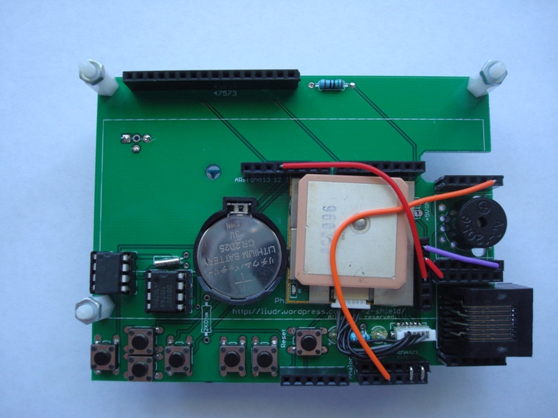
Are you still selling the Phi-2? I am very interested in purchasing one. The inmojo store shows they have none in stock and 3 people are waiting for them.
David,
The 16X2 model is out of stock. I ran out of boards. I have to get more with a lead time of 3 weeks. The 20X4 model just needed an adjustment (adjusting quantity between PCB to kits) and I just did that. Sorry the inmojo has no mechanism to inform me when a particular thing runs out or if people are waiting for more.
are you shipping phi-2 shield 20X4 kit (including LCD)
thnx
Yes. I have kits with LCDs ready for shipping. Here is a link to my inmojo.com store:
http://www.inmojo.com/store/liudr-arduino-and-physics-gadgets/item/phi-2-interactive-arduino-shield-2004/
I prefer this because it keeps track of amount of kits I have in stock and shipping is separated into within USA and international so it’s more fair.
Hi when will you start shipping phi-3
Can you provide the layout files or at least a pdf of the silkscreen layer? I purchased the phi-2 20×4 shield and I’m looking to mount it in a faceplate and I am having a hard time getting the buttons to line up correctly. Thanks!
I’ll post a 1:1 scale PDF. Give me some time.
Hello, I am curious about how to connect the Arduino UNO to the phi-2 shield 4×20. I am a little confused. I am building the alarm clock project for an engineering project that requires an interactive alarm clock, are there any details as to how to connect everything for that specific project?
I have a sample code. I’ll point you to it once I post it. Been maintain it for a few years but just finished updating to make it work on the latest arduino IDE. With this sample code, all things needed are already on the shield, buzzer, buttons and LCD. You can add more functions by wiring more things to it and add some code inside the “alarm” functions. One fellow added servos in the alarm code to make it more physical 😀 .
Do you still have kits available through your inmojo store? It’s showing zero in stock. I have two students that would like to use the kit for a project. I need 2 kits.
Michael,
Thanks for the message. The new circuit boards just arrived so I updated the stock on inmojo.com
Does the kit come pre-assembled or does it come in parts? I would prefer it came in parts so I can have my students piece it together.
Never mind! Just read the description more carefully.
Yep, the shields are kits.
Hello, love the phi-2, am wondering is it possible to ship to Sydney, Australia, as have not had much luck with online stores shipping.
Am relativly new to Arduino, so am still learning, and the phi-2 looks great to learn with.
Cheers
Matthew B
Matthew,
I ship world wide. You can either purchase on my blog or here:
http://www.inmojo.com/store/liudr-arduino-and-physics-gadgets/item/phi-2-interactive-arduino-shield-2004/
Thankyou for the quick reply.
Cheers
Matthew B
Cani bit it from you with the Morse code translater software preloaded? Do I just just need to wire in my key and see my input?
Paul,
That would require an arduino with the code. The shield itself can’t store code. If you’re interested, I can load the code to an arduino compatible board and ship the shield with the arduino for $15 extra.
Hi there,
do you have a European vendor ? or do you ship to Germany ?
How much would shipping be for a pho-2 (phi-3) shield ?
Sorry for the late response. Been very busy. I don’t currently have a European vendor. Would love to have that though. Now shipping to Germany takes many days of first class air mail. I expect USPS to charge about $12 for first class and $33 for priority.
Hello!
I am a highschool student using the Phi-2 shield as an alarm clock. I am currently having trouble installing the programming into the shield. I understand that I must download the phi_prompt, phi_interface, and the phi_big font. But I downloaded the phi_big_font_showcase_v4 saved under user/Arduino/Sketchbook/Libraries and the Arduino IDE software traced an error that phi_big_front.h is no such file or directory?
Also. There are so many files underneath the downloaded libraries. Which version do I use?
Thank you!
Gem-